Transmitting Multiple I/O Points Along A Single Signal Path

Industrial wireless 900 MHz or 2.4 GHz multiple I/O transmitter/receiver
Analynk A16000 Expansion Module provides up to
16 I/O points for wireless transmission or reception.
Wireless transmission of process control signals is steadily increasing in prevalence throughout many industrial environments. The ease of implementation, with no long cable runs to plan, layout, install, protect, and maintain, allows wireless installations to fulfill application niches that may have been considered impractical in the past.

Analynk provides hardware that easily allows the transmission and reception of up to 16 I/O points using a single transmitter and receiver. The A16000 Expansion Module can be configured with up to four internal cards that accommodate various types of input and output signals. The process is similar to setting up the I/O on a PLC. Connect the process signals to the A16000, and the A16000 to one of Analynk's transmitter or receiver devices. Setup is straight forward and allows the installation to be operable in minimal time.

Share your wireless communications and signal transmission challenges with the experts at Analynk and get recommendations on how to best implement workable solutions.


Understanding Telecommunications Terminology

satellite orbiting earth for industrial process control wireless communications
Industrial wireless communications can include satellites
If you are delving into wireless communications for process control operations and expect to go beyond the use of industrial Wi-Fi, you are likely to encounter some concepts and lexicon that may be unfamiliar. A source of recognized standard definitions for industry specific terms will serve as a useful tool for understanding the specifics of radio communications.

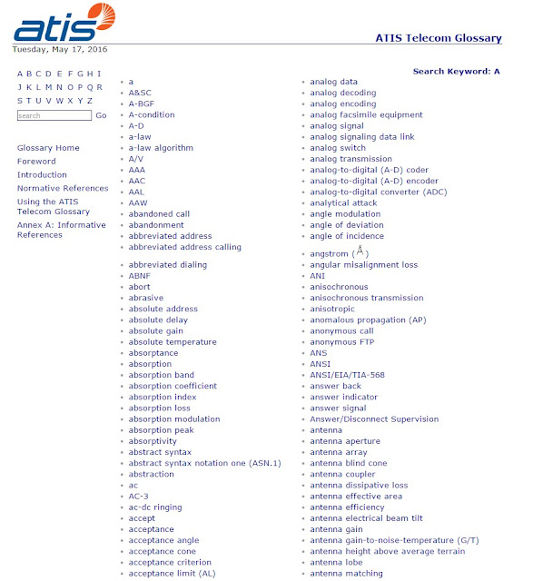
Federal Standard 1037C, entitled Telecommunications: Glossary of Telecommunication Terms was issued by the General Services Administration late in the last century. It was superseded in 2001 by American National Standard T1.523-2001, Telecom Glossary 2000, published by Alliance for Telecommunications Industry Solutions commonly known as ATIS). The current version of the ATIS Telecom Glossary is available for use by the public. Find the glossary website, with its search engine, and either type a term to search for in the box or browse the extensive listings in alphabetical order. It's easy to use and can help you sort out the meanings of some industry specific terms.

Analynk Wireless is a wireless communications equipment provider to the industrial process control sector. Contact the application specialists at Analynk and share your wireless communication challenges.

glossary of telecommunications terms
Screen shot of the glossary, showing search box in upper left area


Understand Fresnel Zones and Their Potential Impact On Your Process Signal Radio Transmission

wire frame rendition of ellipsoid representing Fresnel zone in radio transmission
Rendition of an ellipsoid, the representative shape
of a Fresnel zone
Most of us have been touched by wireless communications in the industrial process control setting. The majority of the installations are likely to be networks that operate similarly to the wireless network you may have in your home. Multiple points communicate through a network controller of some sort. The facility is flooded with signal coverage through multiple access points, so there may not be much need to consider signal propagation. Of course, this is an oversimplification. The point to be made is that, as an operator or implementer, making the actual signal connection is probably not going to be an issue in most cases.
How would you approach an application with a one mile transmission distance?
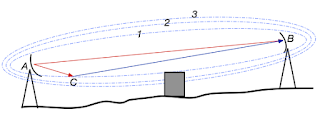
antennas and associated Fresnel zones and obstruction avoidance
Antennas with three Fresnel zones depicted and
obstruction that is outside the primary Fresnel zone
Courtesy Wikipedia
An extended transmission distance across an outdoor area requires more understanding of signal propagation and the factors that can impede the successful delivery of your
process data from transmitter to receiver. One concept that may come into play is the Fresnel zone.

I shall avoid any deep or technical approach to Fresnel zones, as my purpose is to provide the designer, technician, or implementer, who may have limited radio expertise, familiarity with the subject at a level empowering visualization of the concept to recognize the potential for its impact upon achieving a successful project. That said, a Fresnel zone, of which there an infinite theoretical number, is an ellipsoid shaped area extending between transmission and receiving antennas.  While we often consider the transmission path between two points as the popular "line of sight", an unobstructed straight line, radio frequency transmission is more accurately characterized by Fresnel zones. Being aware of the shape of the first, or primary, Fresnel zone for your application is an important element in identifying potential obstructions. A general practice is to keep the primary Fresnel zone at least 60% clear of signal obstructions, in order to maintain high wireless link performance.

There are numerous sources of Fresnel zone calculators online, but a strong recommendation to consult with your selected wireless equipment provider is in order here. Combine their expertise at applying their products with your application knowledge to reach the best outcome.

Introduction to Level Measurement


In many industrial processes, the measurement of level is critical. Depending on the nature of the material being measured, this can be a simple or complex task. Several different technologies for sensing level are briefly explained here.

Level Gauges or Sightglasses
vessel with sight glass level gauge
Sight Glass or Gauge

The simplest form of level measurement for direct measurement of level (almost always visually) in a vessel. A level gauge (sightglass) is usually a clear tube connected to the a vessel at the highest and lowest part of the level range. The fluid level inside the vessel will be at the same hight as the level in the tube.


Floats

tank or vessel with cable and float level indicator
Float level indicator


Another very simple approach to level measurement for fluids or solids is the float. The float sits on
top of the material being measured and is visually, magnetically, or electronically located and equated to the level inside the vessel. It is important that the float material be compatible with the process media and that it freely moves on top of the process.


hydrostatic level measurement
Hydrostatic Pressure

Hydrostatic Level


A very popular way to measure level because of the ease in equating the pressure of a fluid column with the level inside the vessel. In it's simplest form, a pressure sensor (gauge or transmitter) is attached to the bottom of a vessel and measures the pressure of the column. This pressure reading is then interpreted as level.


Bubbler Principle

Bubbler Systems

A variation of the hydrostatic pressure method, bubbler systems measure the pressure of a purge gas being injected into the fluid in a vessel through a dip tube. This approach comes in handy when sensing the level of corrosive fluids. The principle of operation is that the amount of pressure to "push" an inert purge gas through the dip tube will change according to the level in that vessel, and therefore can be correlated to the level.


Displacer Level

Displacer Level

Based upon the laws of buoyancy, a float (either inside its own isolated cage, or hanging in the process directly) is calibrated the the level of the fluid being measured. The displacer is usually a sealed metal tube and hang's in place in the process media. As more of the displacer’s volume becomes submerged, the buoyant force is increased on the making the displacer "lighter".


Radar level measurement device in tank or vessel
Echo level measurement

Echo (Ultrasonic, Radar, Laser)

Level measured by bouncing some wave form (sound, light, electromagnetic) off the surface of liquids and measuring their time of flight.


Radar level measurement device in tank or vessel
Capacitance level measurement

Capacitance Level

Capacitive level instruments measure the electrical capacitance of a conductive rod inserted vertically into a process vessel. As process level increases, the capacitance between the rod and the vessel walls increases, causing a signal change in the instruments circuitry.


Weight

Level is measured by knowing the empty weight of a vessel and the full weigh of a vessel and calibrating the points between. The shape of the vessel is can also be a factor.

Industrial level control requires deep knowledge and understanding of many process variables, such as media compatibility, interfaces, head pressures, material densities, and mechanical considerations. It's always recommended that an experienced consultant be involved with the selection and implementation of any industrial level device.

Image attribution: courtesy of "Lessons In Industrial Instrumentation" by Tony R. Kuphaldt