Refractometry Applications in Industry

In-line refractometer for industrial processing
Courtesy Electron Machine
Refractometry, a combination of physics, materials, and chemistry, is the process which measures the composition of known substances by means of calculating their respective refractive indexes (RI). RIs are evaluated via a refractometer, a device which measures the curve, or refraction, resulting when the wavelength of light moves from the air into and through a tested substance. The unitless number given by the refractometer, usually between 1.3000 and 1.7000, is the RI. The composition of substances is then determined when the RI is compared to a standard curve specific to the material of the substance. There are also four separate types of refractometers: digital, analog, lab, and inline process. Although refractometry can measure a variety of substances, including gases and solids, the most common category of known substances to calculate are liquids; the inline process refractometer is used to quantify the makeup of liquids.

The ultimate focus of industrial refractometry is to describe what is in a final product or output of a process step. A field which relies directly on the results of refractometry is gemology. Gemological refractometry is crucial for accurately identifying the gemstones being classified, whether the gemstones are opaque, transparent, or translucent.

Other common examples of industrial refractometry uses are measuring the salinity of water to determine drinkability; figuring beverages’ ratios of sugar content versus other sweeteners or water; setting eye-glass prescriptions; understanding the hydrocarbon content of motor fuels; totaling plasma protein in blood samples; and quantifying the concentration of maple syrup. Regarding fuels, refractometry scrutinizes the possible output of energy and conductivity, and for drug-testing purposes, refractometry measures the specific gravity, or the density, of human urine. Regarding food, refractometry has the ability to measure the glucose in fruit during the fermentation process. Because of this, those in food services know when fruit is at peak ripeness and, in turn, also understand the most advantageous point in the fruit’s “lifetime” to put it on the market.

The determination of the substance composition of the product examples listed above all speak to the purpose of quality control and the upholding of standardized guidelines; consumers rely on manufacturers not only to produce these products but also to produce these products consistently and identically every single time. Therefore, the success of commercialism, etc. is dependent on maintaining the standards for the composition of substances, i.e. industrial refractometry.

Equipment manufacturers have developed numerous refractometer configurations tailored to specific use and application. Each has a set of features making it the advantageous choice for its intended application. Product specialists can be invaluable sources of information and assistance to potential refractometer users seeking to match the best equipment to their application or process.

Analynk manufactures wireless communications equipment to connect process measurement instruments with remotely located process monitors and controllers. Their products enable customers to make connections across the room, across the plant, across the highway, and around the globe.

Defending Industrial Control Systems From Cyber Threats

binary data stream industrial control system
Industrial control system data cannot be protected by
a fence around the plant site.
Industrial control system owners, operators, and other stakeholders should be aware of their exposure to malicious intrusion and attack by individuals or organizations intent on inflicting physical damage, stealing information, or generally wreaking havoc throughout an industrial operation. The risk of intrusion, regardless of the size or type of facility, is real and deserves the focused attention everyone involved in the design and operation of industrial control systems.

The National Cybersecurity and Communications Integration Center, part of the US Department of Homeland Security, ...
serves as a central location where a diverse set of partners involved in cybersecurity and communications protection coordinate and synchronize their efforts. NCCIC's partners include other government agencies, the private sector, and international entities. Working closely with its partners, NCCIC analyzes cybersecurity and communications information, shares timely and actionable information, and coordinates response, mitigation and recovery efforts. (from www.us-cert.gov/nccic)

The Industrial Control Systems Cyber Emergency Response Team (ICS-CERT) is a division under NCCIC. It has published a set of seven basic steps toward establishing a more secure industrial control system. I have included the publication below, and it is interesting and useful reading for all involved in industrial process control.

Having a fence around an industrial site, with a guarded entry gate, no longer provides the level of security needed for any industrial operation. Read the seven steps. Take other actions to build your knowledge and understanding of the risks and vulnerabilities. Cybersecurity is now another layer of design tenets and procedures that must be added to every control system. It will be a part of your company's best practices and success, now and in the future.

There are uncountable legacy controllers and communications devices throughout industrial America. All need to be reassessed for their vulnerability in the current and upcoming security environment. When reviewing your processes and equipment, do not hesitate to contact Analynk Wireless for assistance in your evaluation of our products.


Solar Powered Wireless Communications for Industrial Process Measurement and Control

solar energy power unit for industrial instruments measurement control
Analynk Model A650 Solar Power Supply
Wireless connections of process measurement and control equipment sometimes are accomplished in remote locations without readily available electric power. Analynk, as part of its full line of industrial wireless connectivity products, provides their model A650 Solar Power Supply for locations that require a small amount of DC power to operate instrumentation and an Analynk transmitter.

The power supply unit comes complete with solar panel, battery, charge controller, and NEMA 4 enclosure. Options are available to accommodate specific installation requirements. Custom units can be designed for larger power requirements and other special applications.

The data sheet below provides more detail. Share your wireless process measurement and control connectivity challenges with Analynk for effective solutions.


Process Connections - Wireless is Simple Solution to Many Challenges

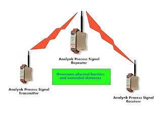
industrial wireless process control connection using transmitter, repeater, receiver
Wireless connections for industrial process signals
The operating personnel at almost every facility have something to which they would like to connect. Remotely located equipment, activities that require a human to be present to monitor operation, and other scenarios are all candidates for a wireless connection. Have you ever thought that it would be helpful to know more about the current status of a remotely located piece of gear, for example, the back-up generator located across the parking lot? Budgets, time constraints, cabling difficulties, and other factors seem to continually outweigh the benefits of making the connection and gathering the data. Those days are gone. In fact, they have been gone for some time.

Industrial wireless transmitters, receivers, and repeaters can be applied in place of wires, cables, conduit, trenches, overhead supports, and all the other hardware associated with a wired installation. Data is gathered using whatever process measurement hardware you prefer, just specify commonly used output signals like 4-20 mA, or a host of others. Connect the measuring device output to the transmitter input. Locate a receiver where you want the sensor information delivered. The transmitter converts the sensor analog signal to digital and the receiver converts back to analog. The connection can be accomplished in a very short amount of time without disturbance to the real estate between the two points.

How can I tell if the wireless connection can be accomplished without interference?
The transmission is accomplished in either the 900 MHz or 2.4 GHz band, delivering adequate range and power for most facility-wide applications. Obstructions can be overcome with the use of a strategically located repeater.
What about power needed to operate the sensors and wireless equipment?
Most process sensors have very small power requirements, as do the Analynk transmission units. Power, if line voltage is not available at the location, can be provided by batteries, or combination of battery and photovoltaic. Little power needs to be provided for operation.

There may be simple and effective wireless solutions to many of your remote monitoring challenges. Don't assume it is difficult, it is not. Don't assume it is expensive, it is not. Share your ideas and challenges with the experts at Analynk. Combining your facility and process knowledge with their technology and product expertise will lead to effective solutions.

Wireless Access Points Installed in Hazardous Locations


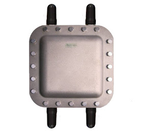
wireless access point enclosure for hazardous area Analynk
Hazardous area wireless access point enclosure
with explosion proof antennas.
Installing the IT department's chosen wireless access point in an area classified as hazardous due to the potential for ignition of flammable or explosive gases and vapors poses a challenge. While there can be real benefit to maintaining uniformity throughout the wireless network hardware, the gear installed in the office areas cannot be installed in a hazardous area without proper accommodation.

Analynk manufactures rated enclosures for industrial wireless access points, facilitating their installation in hazardous locations. Each access point enclosure is specifically targeted and designed to provide easy installation of specific wireless access points from a range of manufacturers. Every model is provided with UL listed explosion proof antennas, a mounting bracket designed for the target access point, and RF cables to make the antenna connections. Enclosures have penetrations specifically located to accommodate the target access point.The current offering accommodates a range of units from Symbol, Cisco, Meru, Aruba, HP, and Motorola, with more models added regularly to accommodate additional wireless access points.
The newly added AP620 is designed for the Motorola/Zebra AP-7532 Access Point
Analynk Wireless specializes in industrial wireless communications. Your wireless communication challenges are welcome at Analynk, so make contact and share your application requirements. Combining your process expertise with Analynk's product specialization will produce an effective solution.


Increasing Generator Set Starting Reliability

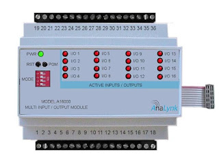
I/O expansion module for industrial wireless transmitter or receiver
Genset monitoring application is ideal for use
of the A16000 Expansion Module
Standby electric generators, often powered by gas or diesel fuel, are critical to maintaining operations in the face of electric power outages. Generator sets for industrial or commercial use are often provided with onboard controls to automatically start the unit, activate a transfer switch, and take the unit back off-line when grid power is restored.

A generator set is a risk mitigation asset, intended to prevent loss of operations when certain adverse conditions occur. Power failures are generally infrequent, so the equipment remains idle most of the time. Automatic controls can test run the unit periodically, but continuous monitoring of a few points on the equipment can provide information that increases the assurance that the unit will start when commanded. Delivering the data to an operations center for monitoring and storage for analysis provides a supervisor a snapshot of unit readiness in real time, anytime.

Some items to monitor that can increase your assessment of startup reliability:

  • Fuel Level - Clearly, knowing the current fuel level is useful. Being able to read the engine fuel level from your operations center saves technician time and provides a continuous means of estimating available generator runtime.
  • Engine Block Heater - Measure the current flowing to the engine block heater to make sure the heater is functioning properly. 
  • Battery - A voltage reading provides indication of battery health.
  • Ambient Temperature - While not essential, logging temperature along with the other items can provide some useful data that may reveal some correlations.
  • Generator Controller Fault Indicators - If the generator control system provides any outputs that will indicate detection of a fault, monitoring their status at the facilities office brings the data to where it can be acted upon immediately.
There may be other aspects of a generator set that can be monitored during standby to increase the assurance of a startup on command. A careful assessment of each system in place will reveal the possibilities.

Analynk manufactures all the transmitters and sensors necessary to deliver the data points needed. With many generators located remotely from the point where the data should be delivered, Analynk's wireless communications products can be employed to deliver all the data from the generator to the facilities or operations center without having to install any cabling between the locations.

Reach out to Analynk with your performance or process monitoring and data delivery challenges. Combing your process and facilities knowledge with their product application expertise will produce effective solutions. 

RTD or Thermocouple for Your Temperature Measurement Application?

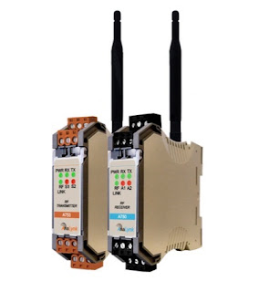
industrial process signal wireless transmitter and receiver
Wireless transmission of temperature signals can be
easily accomplished with Analynk transmitters and receivers
Proper temperature sensor selection is key to getting useful and accurate data for maintaining control of a process. There are two main types of temperature sensors employed for industrial applications, thermocouple and resistance temperature detector (RTD). Each has its own set of features that might make it an advantageous choice for a particular application.

Thermocouples consist of a junction formed with dissimilar conductors. The contact point of the conductors generates a small voltage that is related to the temperature of the junction. There are a number of metals used for the conductors, with different combinations used to produce an array of temperature ranges and accuracy. A defining characteristic of thermocouples is the need to use extension wire of the same type as the junction wires, in order to assure proper function and accuracy.

Here are some generalized thermocouple characteristics.

  • Various conductor combinations can provide a wide range of operable temperatures (-200°C to +2300°C).
  • Sensor accuracy can deteriorate over time.
  • Sensors are comparatively less expensive than RTD.
  • Stability of sensor output is not as good as RTD.
  • Sensor response is fast due to low mass.
  • Assemblies are generally rugged and not prone to damage from vibration and moderate mechanical shock.
  • Sensor tip is the measuring point.
  • Reference junction is required for correct measurement.
  • No external power is required.
  • Matching extension wire is needed.
  • Sensor design allows for small diameter assemblies.

RTD sensors are comprised of very fine wire from a range of specialty types, coiled within a protective probe. Temperature measurement is accomplished by measuring the resistance in the coil. The resistance will correspond to a known temperature. Some generalized RTD attributes:

  • Sensor provides good measurement accuracy, superior to thermocouple.
  • Operating temperature range (-200° to +850°C) is less than that of thermocouple.
  • Sensor exhibits long term stability.
  • Response to process change can be slow.
  • Excitation current source is required for operation.
  • Copper extension wire can be used to connect sensor to instruments.
  • Sensors can exhibit a degree of self-heating error.
  • Resistance coil makes assemblies less rugged than thermocouples.
  • Cost is comparatively higher

Sensors are often part of a transmitter assembly that provides an output signal suitable for connection to controllers or monitoring instrumentation. Challenges of distance can be easily overcome using Analynk's wireless process control connection products. Whether the distance is meters or miles, Analynk has a solution that is effective and simple to apply.

Each industrial process control application will present its own set of challenges regarding vibration, temperature range, required response time, accuracy, and more. Share your process temperature measurement requirements and challenges with a process control instrumentation specialist, combining your process knowledge with their product application expertise to develop the most effective solution.

Specialty Valve for Transmitter Isolation

specialty transmitter isolation valve
Transmitter Isolation Valve
Courtesy PBM Valve Solutions
Fluid process control applications frequently employ tanks and vessels as part of the processing chain or for storage and holding. Level transmitters can be installed on the tank to provide indication of liquid level. While there are numerous combinations of fittings and valves that could be used to mount and connect the transmitter to the tank, one manufacturer, PBM Valve Solutions, has designed a specialized valve intended to mate a transmitter to a tank fitting with great advantage.

The specialized transmitter isolation valve minimizes dead space to prevent media residue buildup. It can be configured to accommodate CIP and drainage without process interruption. Calibration ports and industry standard mountings allow for broad application throughout the fluid process control industries.

Establishing a connection between the transmitter and its associated monitoring or control equipment is a specialty of Analynk Wireless. Analynk provides end to end solutions for delivering transmitter signals using wireless communications that can span across the room or around the globe. Reach out to Analynk for effective and easy to implement wireless solutions.

Analynk's Telmar Brand of Process Control Products

enclosed industrial process controller
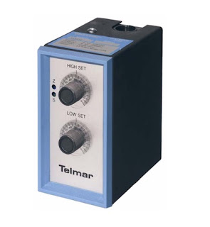
Telmar enclosed 2-wire transmitter
Analynk Wireless, in addition to wireless process signal transmitters, receivers, and repeaters, manufactures a broad line of industrial process control products under the Telmar brand.

  • 2-Wire Transmitters with AC, DC, mA, slidewire, RTD, or tachometer inputs. General purpose enclosure is standard, with options for others to meet any rated environment.
  • 4-Wire Transmitters with dozens of combinations of input and output signals. Alarm outputs available as option.
  •  Signal Alarms that accommodate inputs from thermocouple, DC current, DC voltage, RTD, AC voltage, AC current, tachometer, slidewire, or strain gauge.
  • Pneumatic Transmitters for pressure to current, current to pressure, pressure to voltage, and voltage to pressure applications.
  • Tachometer Transmitters
  • Explosion Proof Transmitters with or without local indicator for thermocouple or RTD input.
    • industrial process transmitter RTD with explosion proof enclosure and display
      RTD transmitter with explosion proof enclosure and display
  • Indicators and Meters with general purpose or explosion proof enclosures in loop powered or external powered versions.
  • Sensor Assemblies for general, corrosive, or explosion proof applications. Thermocouple or RTD.
The Telmar brand provides complementary products for wired process control applications, or can be supplemented by Analynk's wireless products to provide wireless connectivity between point of measurement and point of control.

Reach out to Analynk with your process control challenges, combining your process knowledge with their product expertise to develop effective solutions.

Battery Powered Transmitter for Industrial Wireless Communication

battery powered wireless transmitter in explosion proof enclosure for industrial process control
Battery powered wireless process signal transmitter
in explosion proof enclosure
Industrial settings can present difficult or unique challenges to automation and control designers. Each new challenge seems to be met with a new, improved, or adapted product which fulfills the requirements.

Analynk's standard array of wireless transmitters operate on 24 Vdc. For installations without any appropriate power source, three models are configured to operate on power provided by batteries. The A753-BT transmitters operate on battery power, utilizing a real time clock to schedule transmission intervals appropriate for the application. The transmitter also provides an excitation voltage for external devices. Your sensor's 4-20 mA output provides input to the Analynk transmitter, along with two discrete switches. The transmitter communicates with all of Analynk's receivers.

The unit pictured is configured for use in a hazardous area, with explosion proof enclosure. Other models are suitable for DIN rail mounting in an enclosure of your selection, or provided preconfigured in a NEMA 4 enclosure.

Share your wireless process control connectivity challenges with the experts at Analynk.


Explosion Proof Antennas For Wireless Communications in Hazardous Industrial Settings

explosion proof antenna for industrial wifi wireless communications
CTX Series Explosion Proof Antenna
Analynk
Wireless connections between process measuring and control devices brings several benefits to an industrial operation. The signal cable free installation saves valuable time and space, reduces damage exposure, and simplifies process equipment layout modifications.

Implementing wireless communications in hazardous areas, whether through WiFi or other radio frequency channels, poses a unique set of challenges to successful implementation. Points of network access and other transmission and receiving equipment will require a level of isolation and hardening appropriate for the hazardous industrial environment. Specialized explosion proof enclosures can house the needed equipment, but antennas must extend outside these metal enclosures and into the hazardous environment in order to transmit and receive process signals. This imposes rigorous requirements on antenna design and construction.

Analynk Wireless manufactures patented UL listed hazardous area explosion proof antennas for industrial installations.  Their CTX and CTM series antennas carry an array of third party approvals and are suitable for use in a broad range of hazardous environments. Models can accommodate WiFi and other RF communications across frequency bands commonly utilized in industrial settings, as well as cellular and satellite communications.

Data sheets for the CTX and CTM Series antennas are included below for more detail. Share your wireless communication challenges and application questions with the experts at Analynk and work together to produce the best solutions.

Analynk Further Expands Line of Hazardous Area Wireless Access Point Enclosures

hazardous area wireless access point enclosure with antennas
New AP608 Explosion Proof Access Point Enclosure
For Meru AP-1020e
Analynk Wireless has added three new entries to their line of wireless access point enclosures for use in hazardous areas. Each enclosure is shipped ready for installation of your access point device, with hazardous area antennas, antenna cables, and custom access point mounting bracket included.

Analynk access point enclosures are preconfigured to house a specific manufacturer and model number access point. Review the entire product offering and see the long list of accommodated access points. If you want to use an access point not shown on the list, contact  Analynk for a solution.

The new models and their matching access point.
The hyperlinks above will open data sheets for the respective units.

Analynk manufactures a diverse array of equipment utilized in establishing wireless connections between industrial process control devices. Share your wireless connectivity challenges with the experts at Analynk and get effective solutions.

Analynk Custom Design Services

analynk wireless company logo
Analynk Wireless, in addition to their line of wireless communication products for process monitoring and control, offers custom design services for a broad range of applications in the industrial control arena.

The same engineering and design expertise that goes into every Analynk product can be channeled into specialty products or assemblies for your applications. Whether something as simple as a custom adapter board to facilitate connection between some dissimilar components or an embedded controller with a customized user interface, no application is without a solution.
  • Concept
  • Schematic design
  • PCB design
  • Firmware
  • Prototyping
  • Production
Share your ideas with the design team at Analynk. Combine your expertise with theirs to develop an effective solution.

Flow Control of Slurries and Liquids With Entrained and Suspended Solids

rubber lined pinch valve for industrial application
Cutaway view of  manually
operated pinch valve
Courtesy General Rubber
Industrial process control can involve the manufacture, storage, or transport of almost any imaginable fluid. Media can range from water to concrete, hydrogen gas to steam, and anything in between or outside of those boundaries. Valves are a favored control device for regulating fluid flow and they are available in uncountable varieties, each with particular aspects making them more or less suitable for a particular media or application.

Most industrial valves consist of a body, a stem, and some form of flow obstruction which is located within the media flow path. Operation of the stem repositions the obstruction to allow or block the flow. All of these valve types have a defined sealing surface where the obstruction contacts the body. They also have additional seals where the stem penetrates the body. These design features, while providing certain functions and application advantages, also add to the operational complexity and parts count for the valve.

There is a valve type with a simple operating principle that provides superior performance when the application involves certain media characteristics. It is called a pinch valve, and here is where it excels.
  • Resistance to abrasion and corrosion from slurries or fluids containing suspended solids and the ability to provide tight shutoff around particulates
  • Media and environmental temperature range -40 deg F to +300 deg F
  • Low to moderate operating pressure
  • Flow regulating capability and tight shutoff
  • Non clogging
  • Straight through full bore design with minimal flow resistance
  • Isolation of the valve body and workings from the media
  • Low parts count, low maintenance, easy repair/replacement
A pinch valve consists of a sleeve, through which fluid flows, and a means to compress or "pinch" the sleeve to reduce the open area inside the sleeve. The sleeves are most often fabricated from elastomers with various types of fiber reinforcement. Closure is commonly achieved through movement of one or two bars to squeeze the sleeve, providing throttling or positive closure. The flexibility of the sleeve material allows for tight shutoff, even with fluids containing suspended solids. The valves can be coupled with electric or pneumatic actuators and are available with industry standard connections. One valve variant has a body that can be pressurized to close the sleeve, without the need for a separate actuator. Pinch valves are available with and without an enclosing body.

You should be familiar with the capabilities and forms of this unique valve type. When confronted with certain application challenges, a pinch valve can be a superior solution.

Analynk is committed to excellence in process control, providing wireless communications for process signals, as well as explosion proof enclosures for wireless access points.

Signal Alarms for Process and Operations Monitoring

process control analog signal alarm Telmar Analynk
Telmar 500 Series Signal Alarm
Analynk
Signal alarms provide functionality related to a monitored process condition, which serves as the input to the device. High, low, or both high and low alarm points can be set on the device. When the process condition reaches one of the setpoints, a relay changes state. The relay, rated at 5.0 amperes at 120 VAC, can be used to annunciate the alarm occurrence or activate another device to take some other appropriate action. A number of input options are available that accommodate a broad range of process applications.

  • Thermocouple
  • Millivolt DC
  • RTD
  • AC or DC Current
  • Slide Wire
  • Strain Gauge
  • Tachometer
  • AC or DC Voltage
The standalone signal alarms can be incorporated into new control installations, or added to existing control systems to expand functionality. More information can be found in the data sheet included below, or reach out to Analynk and share your signal or process monitoring challenges and requirements.


Not Your Regular Lightning Protection Scheme

Lightining Strike
Predictive protection for sensitive electrical equipment
from lightning strikes
Lightning strikes constitute extreme releases of energy. A direct hit to your equipment has a high probability of rendering it unusable. The pathways of this destructive energy can be diffuse and unpredictable, leaving the best protection effort as disconnection of electrical equipment from wiring infrastructure and breaking the conductive path into the equipment.

Alokin Industries, manufacturer of Lightning Shield™ protection systems, identifies four threats to electrical equipment that originate from lightning activity.


  • Direct Lightning Strike: Direct lightning strikes to equipment result in high voltages flowing through the equipment grounding path or the circuit serving the equipment.
  • Nearby Lightning Strike: These strikes can induce voltage or current on building infrastructure conductors.
  • Lightning Ground Potential Rise ( L-GPR): This is the electrical energy flowing out from a strike that can saturate a building's grounding system.
  • Off-Voltage Events: Sags and spikes in service line voltage that can damage electrical equipment.
The Lightning Shield™ provides protection by disconnecting electrical equipment when a field energy increase is detected preceding a cloud to ground lightning strike. Isolating equipment from the AC power grid through a positive disconnecting means provides a high level of protection from cloud to ground lightning strikes and their residual impact. The controller will maintain isolated operation for a predetermined amount of time, then switch back to normal AC power. Equipment can be operated from battery or generator sourced power during the isolation period, if needed.

Lightning Shield™ provides predictive protection of electrical equipment by isolating equipment before the occurrence of a cloud to ground lightning strike. The system basically consists of a controller, detector, and whatever disconnecting means (contactor) are needed to accommodate the user's equipment.

Find out more about the Alokin Lightning Shield™, and share your equipment protection challenges with a product application specialist

New Hazardous Area Wireless Access Point Enclosures

Wireless Access point enclosure for hazardous area
Model AP 412 Hazardous Area Access Point Enclosure
Analynk Wireless has added two new entries to their line of wireless access point enclosures for use in hazardous areas. Each access point enclosure is shipped ready for installation of your access point device, with hazardous area antennas, cables, mounting bracket, and antenna cables included.

Analynk access point enclosures are preconfigured to house a specific manufacturer and model number access point. Review the product offering and see the long list of accommodated access points. If you want to use an access point not shown on the list, contact Analynk for a solution.

The new models are designed to house the Cisco 2802E and 3802E Dual Band Access Points. Data sheets for both are included below.

Analynk manufactures a diverse array of equipment utilized in establishing wireless connections between industrial process control devices. Share your wireless connectivity challenges with the experts at Analynk and get effective solutions.


Magnetic Level Indicators For Tank Level Measurement

magnetic level indicator for tank level measurement indication
Magnetic Level Indicator
Courtesy Orion
The magnetic level indicator (MLI), also called a magnetically coupled liquid level indicator or a magnetic level gauge, is in wide-spread use throughout process industries around the world. Originally designed as an alternative to sight glass gauges, MLIs are now commonly specified in new construction and plant expansions.

Principle of Operation

Magnetic level indicators use magnetic force couple the position of a float to a scale that indicates actual liquid level in a tank. The float movement and scale can be used to activate a switch or provide continuous level data via a transmitter. Unlike a sight glass, magnetic coupling allows the MLI to indicate liquid levels without direct contact between the externally-mounted visual indicator and the fluid in the vessel.

A magnetic field consists of imaginary lines of flux originating from the north and south poles and completely surround the magnet. This field acts on other objects (magnets or ferromagnetic materials) through these forces. When a magnetic field acts upon another body with sufficient force to influence it, the pair are said to be magnetically coupled to each other. In the case of a magnetic level indicator, the float is magnetically coupled to the indicator scale.

The MLI float, located inside the chamber and specifically engineered to provide proper buoyancy in the targeted fluid, dynamically tracks the surface of the liquid as it rises and falls. The magnet assembly inside the float generates a magnetic field that penetrates through the chamber wall to couple with the visual indicator.

Typical applications include:
  • Alkylation units 
  • Boiler drums
  • Feedwater heaters
  • Industrial boilers
  • Oil / Water separators
  • Process vessels
  • Propane vessels
  • Storage tanks
  • Surge tanks
  • Wastewater tanks

Advantages of the MLI

A magnetic level indicator is often used in applications where a sight glass (or glass sight gauge) is unsafe, environmentally risky, or difficult to see.

Typical shortcomings of glass sight gauges include:

  • High pressures, extreme temperatures, deteriorating seals, and toxic or corrosive materials may cause a risk of fugitive emission of dangerous substances. 
  • Some chemical materials within a process vessel or storage tank can attack the glass, causing discoloration of the sight gauge, thus decreasing level visibility. 
  • Liquid/liquid interfaces can be very difficult to read in a sight glass particularly if the liquids are of similar color. Clear liquids can also be difficult to see in a sight glass. 
  • Liquids that tend to coat or build-up on surfaces can hinder visibility by forming an opaque film on the glass. 
  • To cover a large measuring span, sight glass assemblies typically must be staggered using multiple sections. 
Key reasons for selecting an MLI over a sight glass are:
  • Improved safety due to the absence of fragile glass and a substantially reduced number of potential leak points. 
  • Greatly increased visibility 
  • Reduced maintenance. 
  • Easier initial installation and addition of transmitters and switches without interrupting the process 
  • Lower long-term cost of ownership and legitimate return-on-investment benefits. 
  • Single chamber measurement over 20 ft. (6 m) without staggering chambers.
When using a transmitter in conjunction with a magnetic level indicator, consider using a wireless connection to deliver the process signal from the transmitter to the monitoring and control unit. Analynk has effective solutions that can be easily implemented. A video shows an application example.

How Far Is Too Far with Wireless Process Signals?

antenna used for industrial wireless communications
Wireless communication technology, adapted for industrial use, has brought a host of benefits to companies bold enough to include it in their process control infrastructure. The use of wireless communications to deliver operating data from sensor to control station is no longer avant garde. The innovators, those first to deploy new technology, have long ago pushed the industrial process control world sufficiently up the learning curve to a point where applying wireless is a fairly straight forward matter.
Are there limits, practical or theoretical, to the length of a wireless connection?
Consider the bandwidth options for wireless transmission of a process signal. The 2.4GHz and 900MHz frequency bands each have their advantages for shorter distances in the range of a few feet to several miles. The ability to connect over any distance is impacted by a number of factors, not the least of which are allowable transmission power level and obstacles to the clear line of sight. One way to extend the range of a device is to install a repeater at some point along the transmission path. Repeaters will receive a fading process signal and transmit the signal at the full available strength, increasing the distance over which the information can be transmitted. Repeaters can also be useful for bypassing obstacles in the transmission path.

What if connection is needed over a longer distance?

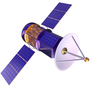
earth orbiting satellite used for process data communications
There are other options for bandwidth that can extend beyond a few miles. If service is available at transmission and receiving sites, cellular networks may be a workable option. Satellite data transmission is also a viable option that can provide global connectivity.

Distance is not really a great hurdle to overcome when it comes to establishing an industrial wireless connection. Share your industrial wireless challenges with application experts. Combining your process knowledge with their wireless expertise will produce effective solutions.

Piping & Instrumentation Diagrams in Process Control

electric power plant
All processes benefit from P&ID
P&ID's (Piping & Instrumentation Diagrams), or Process and Control Flow Diagrams, are schematic representations of a process control system, used to illustrate the piping system, process flow, installed equipment, instrumentation, and functional relationships among all the system components.

Intended to provide a comprehensive picture of all piping and associated hardware, including physical branches, valves, equipment, instrumentation and interlocks, the P&ID employs a set of standard symbols representing each component of the system such as instruments, piping, motors, pumps, etc. The use of standard symbols provides a universal depiction that can be read and understood by operators, technicians, outside contractors, and other similarly trained individuals.

P&ID’s can be very detailed and are generally the primary source from where instrument and equipment lists are generated, also being a very handy reference for maintenance and upgrades. P&ID’s also play an important early role in safety planning by enabling an understanding of the operating states and relationships of all components in the system.


Know Analynk Wireless - Introductory Video


Analynk Wireless is an innovative designer and supplier of wireless instrumentation for the process control industry. Instruments and equipment have been successfully implemented in numerous applications including temperature measurements, 4-20 mA bridges, discrete inputs/outputs, pulse inputs, lighting and pump controls. The company's products are used in both hazardous and non-hazardous locations. Analynk Wireless also manufactures a line of traditional wired process measurement and control instrumentation under the brand name Telmar Instruments.

Share your wireless connectivity challenges with the experts at Analynk. Combining your process knowledge with their expertise with produce effective solutions.

Comparison of 2.4 GHz and 900 MHz for Industrial Process Control Wireless Connection

logo for Analynk Wireless LLC
Wireless transmission of measurement and control signals are the future, and present, of process control. WiFi is already prevalent in higher density environments and providing benefits of reduced cabling and more. Wireless communications also can be used to connect devices over substantial distances, even globally. This article will focus on applications of moderate to long distance that will employ point to point communications of dedicated devices. Here is an illustrated example, with level measurement instruments on storage tanks located remotely from a data monitoring station.

storage tanks with level gauges wireless transmission to data monitoring and control station
Example of wireless connection between remote tanks and data collection and control center
In establishing a wireless process signal connection between the two points in the example, an initial consideration will be whether to employ 900 MHz or 2.4 GHz as the radio band. There are some general implications associated with the selection.

  • Signal attenuation over any distance is greater for 2.4 GHz than 900 MHz. This generally means that 900 MHz can cover a greater distance and provide a signal of sufficient strength to properly communicate.
  • Atmospheric attenuation for either frequency band is about the same, with a very slight advantage to 900 MHz.
  • Both frequencies require "line-of-sight" to provide predictable and reliable operation. Obstructions within that zone can degrade the signal. Any obstructions with dimensions approximating the wavelength of the signal tend to have a greater impact. The wavelength of a 2.4 GHz signal is 12.5 cm (4.52 inches), 900 MHz is 33.3 cm (84.6 inches). 2.4 GHz signals are susceptible to interference by smaller objects in the transmission path than are 900 MHz signals.
  • Without getting too technical, the height of a 900 MHz antenna will need to elevated to a greater distance the that of a 2.4 GHz antenna in order to provide what is known as "free space propagation". This is related to the Fresnel Zone and has greater impact as transmission distance increases.
  • FCC rules allow larger transmit power ratings for 2.4 GHz radio signals than 900 MHz, increasing the potential range for 2.4 GHz.
Evaluate your potential installations with the above points in mind. Their impact on any particular application can vary depending upon the distance, topography, and potential obstructions. Share your wireless communications challenges with the experts at Analynk Wireless. Combining your site and process knowledge with their product application expertise will produce an effective solution.

Analynk Extends Offering of Hazardous Area Access Point Enclosures

explosion proof enclosure for wireless network access point
AP411 for the Meraki MR72 Wireless Access Point
is Analynk's latest addition to the product line
Analynk Wireless manufactures equipment for transmitting process control signals via WiFi, radio, satellite, and cellular networks. One of their continuously expanding product lines is the Hazalynk series of explosion proof access point enclosures for installing wireless access points in hazardous areas.

The company currently has specific models designed for simple accommodation of wireless access points from Symbol, Cisco, Meru, Meraki, Aruba, HP, and Motorola. Each model is specifically configured to house a particular model wireless access point. Antenna openings, cables, and internal mounting bracket are all coordinated to provide easy installation of the wireless access point. Explosion proof antennas suitable for the access point are included with each enclosure.

The latest addition to the product line is intended for use with the Meraki MR72 Access Point. A data sheet for the unit is included below, or you can contact Analynk for more information about this or any of their other industrial wireless products.


Wireless Access Point Installation in Hazardous Area

wireless access point enclosure for hazardous industrial area
Wireless access point enclosure for hazardous area
Here is your challenge. Your facility is expanding its wireless network coverage into another processing area. That new processing area also happens to be classed as hazardous. How are you going to place a wireless access point in that area to provide good wireless coverage?

Analynk Wireless manufactures industrial wireless communications products suitable for use in hazardous areas. One product line, Hazalynk, includes rated enclosures for popular wireless access points to enable installation in hazardous locations. Preconfigured models accommodate units from Cisco, Symbol, Meru, Aruba, Hewlett Packard, Motorola, and other brands. If there is not a preconfigured model for your preferred access point, contact Analynk. Arrangements are possible to accommodate most brands and models.

The Hazardous Area Access Point Enclosures are designed specifically to house the customer's selected access point device. The matching enclosure for an access point will have:
  • Custom mounting bracket mating to the customer's access point.
  • UL listed enclosure for subject hazardous area, including antenna locations coordinated with access point device arrangement.
  • UL listed explosion proof antenna, one or more as need for the subject access point.
  • All hardware, mounting plate, and RF cables to simplify installation and startup
product specialist can help you with the latest available information. Contact Analynk to discuss your application and how to best fulfill your hazardous area wireless communication requirement.

Wireless Communications for Industrial Automation Continues to Expand Because It Performs

communications satellite in Earth orbit
Wireless communications capabilities for process control
extend beyond WiFi
Wireless connection between a sensor and control or monitoring station is not new anymore. Products have matured, familiarity with the technology is widespread. Certainly, there are still large swaths of industrial installations that do not utilize the technology. This can be for any number or reasons, but new industrial technology tends to follow a predictable course throughout its adoption. There will be innovators and early adopters that can justify higher risks with the prospect of great returns. Many industries and companies will wait until perceived technological difficulties with implementation are overcome and products become more mainstream and easy to apply. That is where industrial wireless is today. Assembling complete working systems is a straight forward operation. Costs are comparatively modest. It's easier to visualize a payback.

Let's review some of the benefits a wireless installation can bring.

  • Safety: Wireless connections can reduce personnel exposure to hazardous environments or situations that previously required human intervention or a manual gauge or instrument reading.
  • Easy Scale-up: Adding points on a network is generally a simple incremental process.
  • Operational Advantage: When deployed to replace manual instrument or gauge readings, real time data for diagnostics and efficiency measurements are now available. Information that is more accurate, timely, and consistent will produce better results.
  • Installation Savings: Installation of wireless connected assets has been reported to be up to 10 times less expensive than wired installation. The reduced space and planning for cables and conduit can make what were once complex and time consuming operations much quicker and easier.
  • Mobility: Wireless technology allows for real time connections to mobile platforms. Whether within a plant, on the road, or on the high seas, there are wireless products that can make the connection.
  • Distance: Don't just think WiFi, think radio, think satellite, think cellular. Connections can be established across very long distances using standard products from the industry.
  • Conversion of Legacy Devices: Many existing in-place devices can have their wired connections replaced with a wireless version. This accommodates a staged transition from wired to wireless in facility.
Analynk Wireless manufactures a broad range of wireless communications equipment for industrial process control and automation. Share your wireless connection challenges and ideas with the experts at Analynk and start benefiting from the technology. It's not new anymore. It's mainstream.


Hazardous Area RF Antenna Opens Up Installation Possibilities

Analynk Hazardous Area Antenna
Many industrial process control operations can benefit from wireless connections between measuring and control devices. The absence of cables saves space, reduces potential for damage, and simplifies modifications to the process equipment layout. Implementing wireless communications in hazardous areas, whether through WiFi or other radio frequency channels, presents a particular set of challenges to successful implementation. Points of network access and other transmission and receiving equipment can require a level of isolation and hardening appropriate for the hazardous environment. Specialized enclosures can house the needed equipment, but antennas must extend outside metal enclosures and into the hazardous environment in order to function. This imposes rigorous requirements on antenna design and construction.

Analynk Wireless provides patented hazardous area explosion proof antennas for industrial installations.  Their CTX and CTM series antennas carry an array of third party approvals and are suitable for use in a broad range of hazardous environments. Models can accommodate WiFi and other RF communications across frequency bands commonly utilized in industrial settings, as well as cellular and satellite communications.

Data sheets for the CTX and CTM Series antennas are included below for more detail. Share your wireless communication challenges and application questions with the experts at Analynk and work together to produce the best solutions.


Hazardous Area Wireless Equipment Enclosures Ease the Path to Implementation

hazardous area wireless equipment enclosure with explosion proof antenna
Analynk hazardous area wireless equipment enclosures
are preconfigured for antenna connection.
Extending or establishing wireless connections in hazardous industrial environments presents a unique set of challenges. The equipment must be housed in an enclosure appropriately rated for the environment. Additionally, the antenna must extend outside the hazardous area rated equipment enclosure in order to properly function. The antenna must also carry a suitable rating for the hazardous area and provide an approved mating to the enclosure to preserve the safety integrity of the installation.

Analynk Wireless, innovators in the industrial wireless arena, provide a series of enclosures suitable for Class 1 Division 1 Groups C&D locations, as well as Class 1 Zone 1 applications. The enclosures are preconfigured to accommodate Analynk's hazardous area antenna, which provides access to a range of frequencies that include radio, cellular, and satellite communications.

The company also provides hazardous area rated enclosures for many popular industrial WiFi access points, preconfigured with antennas, equipment mounting bracket, and connection cables.

Share your industrial wireless communications challenges with the experts at Analynk Wireless. Combining your process expertise with their knowledge of wireless communications will produce the best solution.


Transmitting Multiple I/O Points Along A Single Signal Path

Industrial wireless 900 MHz or 2.4 GHz multiple I/O transmitter/receiver
Analynk A16000 Expansion Module provides up to
16 I/O points for wireless transmission or reception.
Wireless transmission of process control signals is steadily increasing in prevalence throughout many industrial environments. The ease of implementation, with no long cable runs to plan, layout, install, protect, and maintain, allows wireless installations to fulfill application niches that may have been considered impractical in the past.

Analynk provides hardware that easily allows the transmission and reception of up to 16 I/O points using a single transmitter and receiver. The A16000 Expansion Module can be configured with up to four internal cards that accommodate various types of input and output signals. The process is similar to setting up the I/O on a PLC. Connect the process signals to the A16000, and the A16000 to one of Analynk's transmitter or receiver devices. Setup is straight forward and allows the installation to be operable in minimal time.

Share your wireless communications and signal transmission challenges with the experts at Analynk and get recommendations on how to best implement workable solutions.