Analynk Wireless manufactures hazardous area wireless access point enclosures and hazardous area wireless antennas. Analynk is also a certified UL508A panel manufacturer providing high quality control panels to Ohio and surrounding areas. For more information, visit the Analynk website here or call 614-755-5091.
How Far Is Too Far with Wireless Process Signals?
Wireless communication technology, adapted for industrial use, has brought a host of benefits to companies bold enough to include it in their process control infrastructure. The use of wireless communications to deliver operating data from sensor to control station is no longer avant garde. The innovators, those first to deploy new technology, have long ago pushed the industrial process control world sufficiently up the learning curve to a point where applying wireless is a fairly straight forward matter.
What if connection is needed over a longer distance?
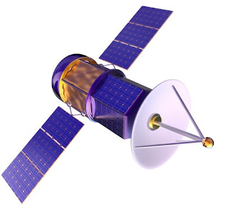
There are other options for bandwidth that can extend beyond a few miles. If service is available at transmission and receiving sites, cellular networks may be a workable option. Satellite data transmission is also a viable option that can provide global connectivity.
Distance is not really a great hurdle to overcome when it comes to establishing an industrial wireless connection. Share your industrial wireless challenges with application experts. Combining your process knowledge with their wireless expertise will produce effective solutions.
Are there limits, practical or theoretical, to the length of a wireless connection?Consider the bandwidth options for wireless transmission of a process signal. The 2.4GHz and 900MHz frequency bands each have their advantages for shorter distances in the range of a few feet to several miles. The ability to connect over any distance is impacted by a number of factors, not the least of which are allowable transmission power level and obstacles to the clear line of sight. One way to extend the range of a device is to install a repeater at some point along the transmission path. Repeaters will receive a fading process signal and transmit the signal at the full available strength, increasing the distance over which the information can be transmitted. Repeaters can also be useful for bypassing obstacles in the transmission path.
What if connection is needed over a longer distance?
There are other options for bandwidth that can extend beyond a few miles. If service is available at transmission and receiving sites, cellular networks may be a workable option. Satellite data transmission is also a viable option that can provide global connectivity.
Distance is not really a great hurdle to overcome when it comes to establishing an industrial wireless connection. Share your industrial wireless challenges with application experts. Combining your process knowledge with their wireless expertise will produce effective solutions.
Piping & Instrumentation Diagrams in Process Control
 |
| All processes benefit from P&ID |
Intended to provide a comprehensive picture of all piping and associated hardware, including physical branches, valves, equipment, instrumentation and interlocks, the P&ID employs a set of standard symbols representing each component of the system such as instruments, piping, motors, pumps, etc. The use of standard symbols provides a universal depiction that can be read and understood by operators, technicians, outside contractors, and other similarly trained individuals.
P&ID’s can be very detailed and are generally the primary source from where instrument and equipment lists are generated, also being a very handy reference for maintenance and upgrades. P&ID’s also play an important early role in safety planning by enabling an understanding of the operating states and relationships of all components in the system.
Know Analynk Wireless - Introductory Video
Analynk Wireless is an innovative designer and supplier of wireless instrumentation for the process control industry. Instruments and equipment have been successfully implemented in numerous applications including temperature measurements, 4-20 mA bridges, discrete inputs/outputs, pulse inputs, lighting and pump controls. The company's products are used in both hazardous and non-hazardous locations. Analynk Wireless also manufactures a line of traditional wired process measurement and control instrumentation under the brand name Telmar Instruments.
Share your wireless connectivity challenges with the experts at Analynk. Combining your process knowledge with their expertise with produce effective solutions.
Comparison of 2.4 GHz and 900 MHz for Industrial Process Control Wireless Connection
 |
| Example of wireless connection between remote tanks and data collection and control center |
- Signal attenuation over any distance is greater for 2.4 GHz than 900 MHz. This generally means that 900 MHz can cover a greater distance and provide a signal of sufficient strength to properly communicate.
- Atmospheric attenuation for either frequency band is about the same, with a very slight advantage to 900 MHz.
- Both frequencies require "line-of-sight" to provide predictable and reliable operation. Obstructions within that zone can degrade the signal. Any obstructions with dimensions approximating the wavelength of the signal tend to have a greater impact. The wavelength of a 2.4 GHz signal is 12.5 cm (4.52 inches), 900 MHz is 33.3 cm (84.6 inches). 2.4 GHz signals are susceptible to interference by smaller objects in the transmission path than are 900 MHz signals.
- Without getting too technical, the height of a 900 MHz antenna will need to elevated to a greater distance the that of a 2.4 GHz antenna in order to provide what is known as "free space propagation". This is related to the Fresnel Zone and has greater impact as transmission distance increases.
- FCC rules allow larger transmit power ratings for 2.4 GHz radio signals than 900 MHz, increasing the potential range for 2.4 GHz.
Evaluate your potential installations with the above points in mind. Their impact on any particular application can vary depending upon the distance, topography, and potential obstructions. Share your wireless communications challenges with the experts at Analynk Wireless. Combining your site and process knowledge with their product application expertise will produce an effective solution.
Analynk Extends Offering of Hazardous Area Access Point Enclosures
 |
| AP411 for the Meraki MR72 Wireless Access Point is Analynk's latest addition to the product line |
The company currently has specific models designed for simple accommodation of wireless access points from Symbol, Cisco, Meru, Meraki, Aruba, HP, and Motorola. Each model is specifically configured to house a particular model wireless access point. Antenna openings, cables, and internal mounting bracket are all coordinated to provide easy installation of the wireless access point. Explosion proof antennas suitable for the access point are included with each enclosure.
The latest addition to the product line is intended for use with the Meraki MR72 Access Point. A data sheet for the unit is included below, or you can contact Analynk for more information about this or any of their other industrial wireless products.
Wireless Access Point Installation in Hazardous Area
 |
| Wireless access point enclosure for hazardous area |
Analynk Wireless manufactures industrial wireless communications products suitable for use in hazardous areas. One product line, Hazalynk, includes rated enclosures for popular wireless access points to enable installation in hazardous locations. Preconfigured models accommodate units from Cisco, Symbol, Meru, Aruba, Hewlett Packard, Motorola, and other brands. If there is not a preconfigured model for your preferred access point, contact Analynk. Arrangements are possible to accommodate most brands and models.
The Hazardous Area Access Point Enclosures are designed specifically to house the customer's selected access point device. The matching enclosure for an access point will have:
- Custom mounting bracket mating to the customer's access point.
- UL listed enclosure for subject hazardous area, including antenna locations coordinated with access point device arrangement.
- UL listed explosion proof antenna, one or more as need for the subject access point.
- All hardware, mounting plate, and RF cables to simplify installation and startup
Subscribe to:
Comments (Atom)


