Showing posts with label hazardous area. Show all posts

From Zones to Safety: Effective Explosion Protection in Industrial Environments

Effective Explosion Protection in Industrial Environments

Industrial hazardous area zoning, a crucial element of explosion protection, plays a pivotal role in ensuring safety and compliance with international standards in areas with potentially explosive atmospheres. These areas pose a significant risk due to the potential presence of flammable gases, vapors, dust, or fibers, which can lead to explosive atmospheres. Identifying and managing these zones is therefore of utmost importance. It involves categorizing different facility sections based on the likelihood of an explosive atmosphere being present, thereby facilitating the implementation of appropriate protective measures and the selection of suitable equipment.

A hazardous area is classified into zones according to the frequency and duration of the presence of explosive atmospheres. Zone 0 indicates an area where an explosive atmosphere is continuously present or for long periods. Such environments require stringent controls and specialized equipment designed to operate safely under these conditions. Zone 1, on the other hand, denotes an area where an explosive atmosphere is likely to occur during normal operations. These zones also require robust protective measures and certified equipment. Finally, Zone 2 refers to areas where an explosive atmosphere is not likely to occur in regular operation, and if it does happen, it will only persist for a short duration.

Explosion protection, in the context of industrial hazardous areas, encompasses a range of technical definitions and methods. Among these, intrinsic safety (IS) stands out as a cornerstone of explosion protection. This approach involves limiting the energy, both electrical and thermal, available for ignition within hazardous areas. By ensuring that the energy levels are below the threshold required to ignite an explosive atmosphere, intrinsic safety provides a reliable means of protection. IS equipment is typically designed to be safe even in the presence of two faults, adding an extra layer of safety.

Another critical method is explosion-proof (Ex d) protection. Equipment designed with this method can withstand an internal explosion of an explosive mixture and prevent the propagation of flames or hot gases to the surrounding environment. Explosion-proof enclosures, typically made from robust materials like cast aluminum or stainless steel, contain any explosions that might occur inside, safeguarding the external environment. It's important to note that this protection method is also known as “flameproof” in some standards.

In addition to intrinsic safety and explosion-proof protection, pressurization (Ex p) is an effective method in some hazardous regions. Pressurized enclosures maintain a higher pressure inside the equipment than the surrounding atmosphere, preventing the ingress of flammable gases or dust. This method ensures that the internal atmosphere remains free from potentially explosive mixtures, thus allowing standard equipment to operate safely in hazardous areas. This method is often used for larger enclosures or rooms, and the pressurized air must be clean and dry to avoid introducing new hazards.

Flameproof (Ex d) protection is another vital technique used in hazardous areas. Equipment with flameproof protection must withstand an internal explosion of an explosive mixture and prevent the propagation of this explosion to the external atmosphere. This method relies on robust enclosures that can contain any explosion, ensuring the surrounding area remains unaffected.

Understanding and applying the concept of gas groups is crucial as it guides the design of equipment for use in hazardous areas. Gases are categorized into different groups based on their ignition temperature and explosion pressure characteristics. Group I includes gases found in mining environments (typically methane), while Groups IIA, IIB, and IIC cover gases found in industrial settings, with Group IIC including highly explosive gases such as hydrogen. Equipment designed for use in hazardous areas must be suitable for the specific gas group present, as this determines the level of protection required.

Temperature classification also plays a critical role in explosion protection. Equipment is classified based on the maximum surface temperature it can reach during operation. This classification ensures that the equipment's surface temperature remains below the ignition temperature of any flammable substances present in the hazardous area. These classifications are denoted as T1 to T6, with T1 being the highest ignition temperature and T6 being the lowest. By adhering to temperature classifications, industries can minimize the risk of igniting an explosive atmosphere.

Implementing these explosion protection methods requires a thorough understanding of the hazards in an industrial setting. Risk assessments, such as hazard and operability studies (HAZOP) and layers of protection analysis (LOPA), are essential. Regular inspections and adherence to international standards such as the IEC 60079 series are fundamental to maintaining safety. The IEC 60079 series provides comprehensive guidelines for the classification, installation, maintenance, and inspection of equipment in hazardous areas. For instance, IEC 60079-14 covers the selection and installation of equipment, and IEC 60079-17 addresses inspection and maintenance.

Industrial hazardous area zoning and explosion protection are critical to ensuring safety in environments with potentially explosive atmospheres. By accurately classifying hazardous areas and applying appropriate protection methods such as intrinsic safety, explosion-proof protection, and pressurization, industries can mitigate risks and safeguard both personnel and property. Adhering to international standards and conducting regular assessments further enhances the effectiveness of these measures, creating a safer industrial landscape.


Hazardous Area Enclosures Facilitate Plant Standards for Wireless Access Points

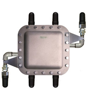
Hazardous Area Enclosures for Access Point
Hazardous area enclosures for wireless access point.
(Analynk)
There are often conflicts between what is needed and what is desired in many technical endeavors, and the field of industrial process control is no exception. Such a conflict between process engineers and IT managers was created by the incursion and popularity of wireless communication into the field of process measurement and control. It is, of course, a cooperative and friendly conflict, but a condition which may require some incompatible interests to be resolved.

For a number of reasons, compliance with certain norms set for the organization's wider scope and standards is advantageous for the wireless network equipment. Standardization on specific brands or hardware types can have true advantages. The tasks associated with network infrastructure back end management are less complicated when all equipment belongs to the same producer and family of products. Provisioning, which includes initial set-up, long-term management and management of unit losses, is simplified when all units are identical. The same objective is pursued by process technicians and operators in standardizing specific transmitters, valves or other parts that have various facilities throughout a plant.

The AE902-1 is designed to house the Aruba AP-318
The Analynk AE902-1 is designed to house the Aruba AP-318.
The problem occurs when the access point selected by the IT team, with all the latest standards, needs to be installed in a part of the plant categorized as hazardous (owing to the potential for flammable or explosive gases, vapors or dusts that can be ignited). There is a solution, actually a fairly simple one. Use a non-hazardous area access point (as specified or designated by the IT department) and installing it inside an access point enclosure designed for hazardous areas.

Analynk Wireless manufactures enclosures for industrial wireless access points installed in hazardous locations.  Each access point enclosure is provided with agency approved enclosures, antennas, mounting, penetrations, cabling, and power supplies. Their current product offering accommodates a wide range of wireless access point manufacturers including Symbol, Cisco, Meru, Aruba, HP, and Motorola.  Access point and Wi-Fi technology technologies change rapidly. Wireless component lifecycles are relatively short compared to other process equipment. The use of hazardous area access point enclosures provide flexibility and convenience in access point selection and upgrades.

For more information, contact Analynk Wireless by visiting https://analynk.com or by calling 614-755-5091.

Regulations and Standards for Equipment Operating in Explosive Atmospheres

Reprinted from "Built to Blast: Industrial Internet of Things Infrastructure for Hazardous Environmentsby Aruba Networks.  Full text white paper can be downloaded here.

A potentially explosive atmosphere exists when air gas, vapor, mist, or dust – alone or in combination – are present under circumstances in which it or they can ignite under specified operating conditions. Places with potentially explosive atmospheres are called “hazardous” or “classified” areas or locations.

Multiple local and international regulations are in place to mitigate the risk posted by operating networks and IoT devices in potentially explosive atmospheres. Increasingly these regulations are becoming harmonized under a framework developed by the International Electrotechnical Commission (IEC) and European and US standards.

ATEX Directives

ATEX, derived from the French phrase “Atmosphères Explosibles,” is a European regulatory framework for the manufacture, installation, and use of equipment in explosive atmospheres. It consists of two European Union (EU) directives:

  • 1999/92/EC which defines the minimum safety requirements for workers in hazardous areas; and
  • 2014/34/EU which covers equipment and protective systems intended for use in potentially explosive atmospheres.

These two directives define the essential health and safety requirements, as well as the conformity assessment procedures, that need to be applied before products can be used in the EU market.

IEC Ex System (IECEx)

IECEx is a voluntary certification program that validates compliance with IEC standards related to safety in explosive atmospheres. Details about IECEx, its coverage areas, and conformity mark system can be found at www.iecex.com.

European Committee for Electrotechnical Standardization (CENELEC)

CENELEC was formed to facilitate a consensus-building process between European and international electrical standards activities. In 1996 CENELEC and the IEC formalized a framework of cooperation through an agreement on common standards planning and parallel voting that is known as the Dresden Agreement. As a result of this initiative both CENELEC and IEC have similar standards for explosive environments.

National Electrical Code (NEC)

NEC defines the standards for the safe installation of electrical wiring and equipment in the United States, and its standards are coordinated with those of the National Fire Protection Association (NFPA). NFPA 70 Articles 500 thru 510 address safe practices for the location and operation of electrical equipment in hazardous locations installations.
Additional national standards relating to hazardous environments may be in effect in different countries, however, there has been a concerted effort in recent years to harmonize local standards with the standards referenced above.

About Analynk

Analynk, LLC manufacturers hazardous area wireless access points. More information on their products can be found here.
https://analynk.com
614-755-5091

IIoT (Industrial Internet of Things) Wireless Networking Considerations in Hazardous Environments

Industrial Internet of Things Wireless Networking
BUILT TO BLAST
Industrial Internet of Things Infrastructure for
Hazardous Environments
Industry groups and standards bodies have collaborated to address these issues by classifying explosive materials and defining standards under which networking equipment and Internet of Things (IoT) devices can be safely operated in their presence. The work has been conducted by different organizations, in different regions, and it can be challenging to understand which standards are applicable under different scenarios.

This white paper examines the different categories of explosive risks, which standards to apply under different scenarios, how network infrastructure can be deployed in explosive environments, and how sensor systems can be integrated with this infrastructure. The goal is to enable end customers and resellers to select the network infrastructure, enclosures, and associated systems that are best suited to each scenario.

Methods of Isolating Electrical Equipment in Hazardous Areas

Background

Combustion or fire is a chemical reaction in which a combustible material combines with an oxidant to release energy. Part of the energy release is used to sustain the explosion, by utilizing existing heat or creating a vacuum to consume more oxygen.  Within a hazardous environment there are three elements necessary for a fire or explosion:
  • A combustible material also known as a fuel 
  • Ignition source - electrical arcing or general heat
  • An oxidizer also known as oxygen
When a fuel, oxidizer and ignition source are present at the necessary levels, burning or explosion will occur. To reduce the possibility of fire or explosion, one of the key elements needs to be reduced or removed.

Another key factor in a fire or explosion are the explosive limits. These are the maximum and minimum concentration needed of a given combustible material to support a fire or explosion. To form an explosive mixture, the hazardous gas must have sufficient concentration levels. The minimum concentration of oxygen to combustible material is known as the lower explosive limit or LEL. If the concentration is below the LEL, it will not be flammable or have enough flammable material present. The same condition would apply if gas concentration is too rich, meaning it will not ignite because it will not have sufficient oxygen to sustain the fire or explosion. This is known as the upper explosive limit, or UEL. It should be noted that different gases will have different threshold limits.

In addition to the explosive limits, each hazardous material will have an autoignition temperature and a flashpoint. The flashpoint is the temperature at which the material will generate sufficient quantity of vapor to form an ignitable mixture. As the liquid is heated and reaches the flashpoint, autoignition could occur. An autoignition is the lowest temperature at which a combustible material will spontaneously ignite in a normal atmosphere. For example, if we have the heating of a combustible liquid, explosive vapors are created. As the material reaches the explosive limits creating the flashpoint. If the general atmosphere is increased, the autoignition temperature, fire, or explosion will occur.

To simplify, the specification of electrical devices into hazardous environments, IEC classification methods utilize autoignition, flashpoint, and explosive limits to place hazardous materials within groups.

The two predominant methods used for classification of hazardous environments are the NEC and IEC standards. IEC and NEC standards both classify the level of risk into three main categories:
  • Continuous
  • Occasional
  • Not normally present
All three categories provide the likelihood of an explosive atmospheric condition within the general environments. Within the IEC standard, the general risk categories are then classified as Zones. This reflects the physical material that could provide a potential fire or explosion. From liquids and gases, the area classifications are Zone 0, Zone 1, and Zone 2. By altering the physical material to dust or fibers, the area classification numerical value changes to Zone 20, Zone 21, and Zone 22.

Referring back to the necessary requirements for an explosive triangle, we know we need ignition source, oxygen, gas and or dust combustible material in the correct mixture within the atmosphere. In order to specify electrical devices and hazardous locations, we need to identify the general Zones within each area. When working with liquids or gas, we locate the most hazardous or flammable location directly above the material. Due to the possibility of the valve leaking, at the top of the containment structure we must classify the area as Zone 1. As we move further away from the possible explosive atmospheric condition the Zone classification would be reduced to Zone 2. By altering the combustible material properties to a solid form, the area classification above the material would be Zone 20. If the dust escapes the same failed valve, the external area around the same containment unit would be classified as Zone 21. As we continue to move away from the containment unit and with reduction of Category risk, the new classification for the general area would be Zone 22.

Now that we know combustible materials whether liquid, gas and or dust will have different upper and lower explosive limits, and we understand the general heat could be the ignition source, within the IEC standards the T rating specifies the maximum surface temperature an electrical device will create. As the temperature increases, the associate rating will decrease, meaningless heat will have a higher T rating, while an increase in surface temperature will reduce the T number.

As a recap the IEC standards classify hazardous areas as environments that could contain explosive vapors, gases, and/or dust within the atmosphere. The primary categories provide the risk levels as constant, occasional, and not likely. Since elements have a variety of flammability and the physical properties could be different, IEC standards segment the types of combustible materials into Zone classifications. The most hazardous is Zone 0 or Zone 20. By reducing the risk level to have occasional explosive atmospheres the Zone classification is Zone 1 or Zone 21 and further reduction of Category risks would change the hazards classification to Zone 2 or Zone 22
Flameproof enclosure
Flameproof enclosure for
wireless access point (Analynk

Methods of Isolation/Protection

Let's take a look at each method of protection and the general application. To ensure safety in a given situation, equipment is placed in protective level categories. As mentioned before Category 1 is the highest safety level, making Category 3 the lowest risk and safety level. The general 8 protective methods are:
  1. Flameproof enclosures
  2. Sand encapsulation
  3. Pressurization 
  4. Oil encapsulation 
  5. General encapsulation
  6. Increased safety
  7. Intrinsic safety
  8. Non-sparking
A flameproof enclosure method is a type of protection where devices that are capable of igniting an explosive atmosphere are built inside an enclosure. This protective method prevents the transmission of the explosion to the external atmosphere surrounding the enclosure. This method of protection would be suitable for applications on:
  • Power operated equipment
  • Switchgear
  • Motors
  • Any equipment that produces ignition source during normal operation.
Sand encapsulation is a type of protection in which the enclosure of the electrical apparatus is filled with a finely granulated material. This ensures electrical arcs occurring within the electrical apparatus will not ignite the surrounding atmosphere.

Pressurization is a method of protection by which the entry of a surrounding combustible material is prevented by maintaining a protective gas within the enclosure. This is generally accomplished by creating a higher pressure within the enclosure than the surrounding atmosphere. This protective method would be used for any power operated equipment.

Oil encapsulation is a type of protection in which the electrical apparatus or part of the electrical apparatus are immersed within an oil-based fluid. The general application for this type of protection would be used for:
  • Switchgear units
  • Circuit breakers
  • Transformers
Encapsulation is a type of protection in which the device that could ignite anexplosive atmosphere are enclosed within a resin. The material used would be resistant to environmental influences, heat and/or sparking from electrical components. The general application for this protective method would be used for:
  • Electrical circuit boards
  • Miniature motors
  • Valves
Increased safety is a type of protection where measures are taken to prevent the possibility of high temperatures and the occurrence of ignition. This method includes the interior and external portions of the electrical apparatus. The general application for this protective method would include:

Connection and distribution boxes
Luminaires
Measuring instruments and devices that do not normally produce ignition within operation

Intrinsic safety is a protective method to ensure that the available electrical and thermal energy in the system is always low enough that the ignition of the hazardous atmosphere cannot occur. This is achieved by ensuring that only low voltages and currents enter the hazardous area as well as all electrical supply and signal wires are protected by safety barriers. The general application for intrinsic safety would be used for:
  • Measuring and control engineering 
  • Data engineering
  • Low electrical valves
Non-sparking equipment and wiring process is a protective method where apparatuses are designed with low power levels and low stored energy. This ensures that arc produced during normal functionality of the equipment,  or as the result of equipment failure,  has insufficient energy to ignite the hazardous atmosphere. The general application for non-sparking protective methods would be used for:
  • Motors
  • Lighting
  • Junction boxes
  • Electrical equipment
All equipment certified for use in hazardous areas must be labeled to show the type and level of protection applied.

In summary hazardous locations could exist in multiple industries. The geographical location will dictate the general method used for classification. The European Standard or IEC provides guidance of risk into three main categories. These risk levels are then divided into Zones and have numerical values that relate to the possibility of explosive gases or dusts present within the atmosphere. Because combustible material could have a variety of explosive limits, the method of protection will be important. Nevertheless all electrical devices placed within hazardous environments will follow the device markings to ensure fire or explosion does not occur.

Safely Locate Your Aruba AP 318 in Hazardous Areas with this New Enclosure

Analynk AE902 Hazardous Area Access Point Enclosure
Wi-Fi coverage is increasingly required in all areas of the modern industrial manufacturing plant. Adding wireless access points in non-hazardous areas, in an environmentally protected structure, is relatively simple. Many times the access point's own enclosure is all the protection required for that service.

On the other hand, creating a reliable wireless data transmission network in locations with dangerous concentrations of flammable gases or ignitable dust present unique network challenges. Industries such as off-shore drilling, petrochemical refining and mining require wireless networking components rated for use in hazardous areas.

Hardened access points, such as the Aruba Networks AP 318, are built for rugged environments. The AP 318 is capable of operating from -40 F. up to +140 F., and the unit's enclosure provides water and dust protection. However, if the access point is being located in a hazardous area (an area where flammable vapor, gas or dust exist) it will have to be mounted inside a hazardous area access point enclosure.

The Analynk AE902 Hazardous Area Access Point Enclosure provides the approvals and features required for hazardous area applications. Designed specifically to house the Aruba AP 318 access point, the AE902 enclosure allows facilitates the deployment of wireless networks in Class I, Division 2, groups A, B, C, & D areas, and combines protection for harsh, wet and corrosive environments. It includes a NEMA 4X rating to withstand driving rain, blowing sand, dust, splashing, and an occasional hose down. Finally, the AE902 comes complete with a PoE (Power over Ethernet) injector and AC to DC power supply for simplified wiring.

New Product Alert: AE902-1 Hazardous Area Class I, Division 2, Access Point Enclosure for Aruba AP 318

AE902-1
The Analynk AE902-1
Analynk is proud to announce a new access point enclosure, the AE902-1, specifically for the Aruba AP-318 access point.

Aruba, a Hewlett Packard Enterprise company, developed the Aruba 318 series access point as a hardened device for use in harsh, weather-protected environments. Aruba designs some of the most popular and highly rated access points in the industry.
Aruba AP-318
Aruba AP-318

Analynk developed the AE902-1 to house the Aruba AP-318 for use in hazardous areas. The enclosure, all hardware and antennas are rated for Class I, Division 2, groups A, B, C, & D. 

A POE (Power over Ethernet) injector and AC to DC power supply, are included. The enclosure is made of 316 stainless steel and has a NEMA 4X rating for harsh conditions, such as offshore oil and gas platforms. Optional directional antennas are available, and antennas can be mounted up to 150’ away from the enclosure. The AE902-1 can be flat panel or pole mounted.

As mentioned above, the AE902-1 is currently rated Class I, Division 2 Groups, A, B, C, & D. ATEX Zone 2 approval is pending.

See the drawing below. For more detailed information, inquiries, or to download a Sales Specification Sheet, visit this page on the Analynk website.

Analynk, LLC
https://analynk.com
(614) 755-5091

AE902-1
Click for larger view.

HazaLynk™ Wireless Products for Hazardous Areas

The HazaLynk™ Series incorporates a wide selection of wireless hazardous area devices to suit a variety of industrial applications. The product line includes wireless instruments for hazardous areashazardous area antennas, hazardous area access point enclosures, and hazardous area RF enclosures that simplify the process of installing field instrumentation, while meeting code requirements for hazardous classified and explosive environments.

https://analynk.com
(614) 755-5091


Hazardous Area Classifications

Hazardous AreaWhen electrical equipment is used in, around, or near an atmosphere that has flammable gases, vapors, or flammable liquids, there is always a possibility or risk that a fire or explosion might occur. Those areas where the possibility or risk of fire or explosion might occur due to an explosive atmosphere and/or mixture is often called a hazardous (or classified) location/area.

Currently there are two systems used to classify these hazardous areas; the Class/Division system and the Zone system. The Class/Division system is used predominately in the United States, whereas the rest of the world generally uses the Zone system.

Class/Division System

Hazardous locations per the Class/Division system are classified according to the Class, Division, and Group.
  1. Class - The Class defines the general nature (or properties) of the hazardous material in the surrounding atmosphere which may or may not be in sufficient quantities.
    • Class I - Locations in which flammable gases or vapors may or may not be in sufficient quantities to produce explosive or ignitable mixtures.
    • Class II - Locations in which combustible dusts (either in suspension, intermittently, or periodically) may or may not be in sufficient quantities to produce explosive or ignitable mixtures.
    • Class III - Locations in which ignitable fibers may or may not be in sufficient quantities to produce explosive or ignitable mixtures.
  2. Division - The Division defines the probability of the hazardous material being able to produce an explosive or ignitable mixture based upon its presence.
    • Division 1 indicates that the hazardous material has a high probability of producing an explosive or ignitable mixture due to it being present continuously, intermittently, or periodically or from the equipment itself under normal operating conditions.
    • Division 2 indicates that the hazardous material has a low probability of producing an explosive or ignitable mixture and is present only during abnormal conditions for a short period of time.
  3. Group - The Group defines the type of hazardous material in the surrounding atmosphere. Groups A, B, C, and Dare for gases (Class I only) while groups E, F, and G are for dusts and flyings (Class II or III).
    • Group A - Atmospheres containing acetylene.
    • Group B - Atmospheres containing a flammable gas, flammable liquid- produced vapor, or combustible liquid- produced vapor. Typical gases include hydrogen, butadiene, ethylene oxide, propylene oxide, and acrolein.
    • Group C - Atmospheres containing a flammable gas, flammable liquid- produced vapor, or combustible liquid- produced vapor. Typical gases include hydrogen sulfide, ethyl either, ethylene, and acetaldehyde.
    • Group D - Atmospheres containing a flammable gas, flammable liquid- produced vapor, or combustible liquid- produced vapor. Typical gases include acetone, ammonia, benzene, butane, ethanol, gasoline, methane, natural gas, naphtha, and propane.

Zone System

Hazardous locations per the Zone system are classified according to its Zone. For gas atmospheres electrical equipment is further divided into Groups and Subgroups.

The Zone defines the probability of the hazardous material (gas), being present in sufficient quantities to produce explosive or ignitable mixtures.
  • Gas
    • Zone 0 - Ignitable concentrations of flammable gases or vapors which are present continuously or for long periods of time.
    • Zone 1 - Ignitable concentrations of flammable gases or vapors which are likely to occur under normal operating conditions.
    • Zone 2 - Ignitable concentrations of flammable gases or vapors which are not likely to occur under normal operating conditions and do so only for a short period of time.
  • Group - Electrical equipment used in gas atmospheres is divided into two groups.
    • Group I - Equipment used in mines with atmospheres containing methane or gases and vapors of equivalent hazard. (Note: Group I does not apply to offshore and is shown for information purposes only).
    • Group II - All other equipment; which is further subdivided into three subgroups.
      • Group IIA - Atmospheres containing propane, or gases and vapors of equivalent hazard.
      • Group IIB - Atmospheres containing ethylene, or gases and vapors of equivalent hazard.
      • Group IIC - Atmospheres containing acetylene or hydrogen, or gases and vapors of equivalent hazard.
Reprinted from The Bureau of Safety and Environmental Enforcement
https://www.bsee.gov

Hazardous Area Antennas Now Carry NEMA 4X Rating

hazardous area antenna for industrial wireless communications
The CTX and CTM antennas for industrial wireless
communications now carry a NEMA 4X rating
Analynk is well known in the industrial wireless communications field for its hazardous area antennas. Recently, certification was received as RoHS compliant. Analynk has now achieved a NEMA 4X rating for the CTM and CTX hazardous area explosion proof antennas, further expanding the range of applications and solidifying the product's reputation for high performance and ruggedness.

Data sheets for both the CTM and CTX series antennas are provided below, but sharing your industrial wireless communications challenges with the experts at Analynk Wireless is always the best path to an effective solution.


New Wireless Access Point Enclosure For Hazardous Areas

hazardous area wireless access point enclosure
New Model AP622 Access Point Enclosure
Analynk manufactures enclosures for industrial wireless access points, facilitating their installation in hazardous locations. Each access point enclosure is specifically targeted and designed to provide easy installation of specific wireless access points from a range of manufacturers. Every model is provided with UL listed explosion proof antennas, a mounting bracket designed for the target access point, and RF cables to make the antenna connections. Enclosures have penetrations specifically located to accommodate the target access point.The current offering accommodates a range of units from Symbol, Cisco, Meru, Aruba, HP, and Motorola, with more models added regularly to accommodate additional wireless access points.

The newly added AP622 is designed for the Aruba AP-304 dual band access point. Analynk Wireless specializes in industrial wireless communications. Your wireless communication challenges are welcome at Analynk, so make contact and share your application requirements. Combining your process expertise with Analynk's product specialization will produce an effective solution.

The datasheet for the new model is provided below. You can see all the models and their companion access points on the Analynk site.


Wireless Access Points Installed in Hazardous Locations


wireless access point enclosure for hazardous area Analynk
Hazardous area wireless access point enclosure
with explosion proof antennas.
Installing the IT department's chosen wireless access point in an area classified as hazardous due to the potential for ignition of flammable or explosive gases and vapors poses a challenge. While there can be real benefit to maintaining uniformity throughout the wireless network hardware, the gear installed in the office areas cannot be installed in a hazardous area without proper accommodation.

Analynk manufactures rated enclosures for industrial wireless access points, facilitating their installation in hazardous locations. Each access point enclosure is specifically targeted and designed to provide easy installation of specific wireless access points from a range of manufacturers. Every model is provided with UL listed explosion proof antennas, a mounting bracket designed for the target access point, and RF cables to make the antenna connections. Enclosures have penetrations specifically located to accommodate the target access point.The current offering accommodates a range of units from Symbol, Cisco, Meru, Aruba, HP, and Motorola, with more models added regularly to accommodate additional wireless access points.
The newly added AP620 is designed for the Motorola/Zebra AP-7532 Access Point
Analynk Wireless specializes in industrial wireless communications. Your wireless communication challenges are welcome at Analynk, so make contact and share your application requirements. Combining your process expertise with Analynk's product specialization will produce an effective solution.


New Hazardous Area Wireless Access Point Enclosures

Wireless Access point enclosure for hazardous area
Model AP 412 Hazardous Area Access Point Enclosure
Analynk Wireless has added two new entries to their line of wireless access point enclosures for use in hazardous areas. Each access point enclosure is shipped ready for installation of your access point device, with hazardous area antennas, cables, mounting bracket, and antenna cables included.

Analynk access point enclosures are preconfigured to house a specific manufacturer and model number access point. Review the product offering and see the long list of accommodated access points. If you want to use an access point not shown on the list, contact Analynk for a solution.

The new models are designed to house the Cisco 2802E and 3802E Dual Band Access Points. Data sheets for both are included below.

Analynk manufactures a diverse array of equipment utilized in establishing wireless connections between industrial process control devices. Share your wireless connectivity challenges with the experts at Analynk and get effective solutions.


Analynk Extends Offering of Hazardous Area Access Point Enclosures

explosion proof enclosure for wireless network access point
AP411 for the Meraki MR72 Wireless Access Point
is Analynk's latest addition to the product line
Analynk Wireless manufactures equipment for transmitting process control signals via WiFi, radio, satellite, and cellular networks. One of their continuously expanding product lines is the Hazalynk series of explosion proof access point enclosures for installing wireless access points in hazardous areas.

The company currently has specific models designed for simple accommodation of wireless access points from Symbol, Cisco, Meru, Meraki, Aruba, HP, and Motorola. Each model is specifically configured to house a particular model wireless access point. Antenna openings, cables, and internal mounting bracket are all coordinated to provide easy installation of the wireless access point. Explosion proof antennas suitable for the access point are included with each enclosure.

The latest addition to the product line is intended for use with the Meraki MR72 Access Point. A data sheet for the unit is included below, or you can contact Analynk for more information about this or any of their other industrial wireless products.


Wireless Access Point Installation in Hazardous Area

wireless access point enclosure for hazardous industrial area
Wireless access point enclosure for hazardous area
Here is your challenge. Your facility is expanding its wireless network coverage into another processing area. That new processing area also happens to be classed as hazardous. How are you going to place a wireless access point in that area to provide good wireless coverage?

Analynk Wireless manufactures industrial wireless communications products suitable for use in hazardous areas. One product line, Hazalynk, includes rated enclosures for popular wireless access points to enable installation in hazardous locations. Preconfigured models accommodate units from Cisco, Symbol, Meru, Aruba, Hewlett Packard, Motorola, and other brands. If there is not a preconfigured model for your preferred access point, contact Analynk. Arrangements are possible to accommodate most brands and models.

The Hazardous Area Access Point Enclosures are designed specifically to house the customer's selected access point device. The matching enclosure for an access point will have:
  • Custom mounting bracket mating to the customer's access point.
  • UL listed enclosure for subject hazardous area, including antenna locations coordinated with access point device arrangement.
  • UL listed explosion proof antenna, one or more as need for the subject access point.
  • All hardware, mounting plate, and RF cables to simplify installation and startup
product specialist can help you with the latest available information. Contact Analynk to discuss your application and how to best fulfill your hazardous area wireless communication requirement.

Hazardous Area RF Antenna Opens Up Installation Possibilities

Analynk Hazardous Area Antenna
Many industrial process control operations can benefit from wireless connections between measuring and control devices. The absence of cables saves space, reduces potential for damage, and simplifies modifications to the process equipment layout. Implementing wireless communications in hazardous areas, whether through WiFi or other radio frequency channels, presents a particular set of challenges to successful implementation. Points of network access and other transmission and receiving equipment can require a level of isolation and hardening appropriate for the hazardous environment. Specialized enclosures can house the needed equipment, but antennas must extend outside metal enclosures and into the hazardous environment in order to function. This imposes rigorous requirements on antenna design and construction.

Analynk Wireless provides patented hazardous area explosion proof antennas for industrial installations.  Their CTX and CTM series antennas carry an array of third party approvals and are suitable for use in a broad range of hazardous environments. Models can accommodate WiFi and other RF communications across frequency bands commonly utilized in industrial settings, as well as cellular and satellite communications.

Data sheets for the CTX and CTM Series antennas are included below for more detail. Share your wireless communication challenges and application questions with the experts at Analynk and work together to produce the best solutions.


Hazardous Area Wireless Equipment Enclosures Ease the Path to Implementation

hazardous area wireless equipment enclosure with explosion proof antenna
Analynk hazardous area wireless equipment enclosures
are preconfigured for antenna connection.
Extending or establishing wireless connections in hazardous industrial environments presents a unique set of challenges. The equipment must be housed in an enclosure appropriately rated for the environment. Additionally, the antenna must extend outside the hazardous area rated equipment enclosure in order to properly function. The antenna must also carry a suitable rating for the hazardous area and provide an approved mating to the enclosure to preserve the safety integrity of the installation.

Analynk Wireless, innovators in the industrial wireless arena, provide a series of enclosures suitable for Class 1 Division 1 Groups C&D locations, as well as Class 1 Zone 1 applications. The enclosures are preconfigured to accommodate Analynk's hazardous area antenna, which provides access to a range of frequencies that include radio, cellular, and satellite communications.

The company also provides hazardous area rated enclosures for many popular industrial WiFi access points, preconfigured with antennas, equipment mounting bracket, and connection cables.

Share your industrial wireless communications challenges with the experts at Analynk Wireless. Combining your process expertise with their knowledge of wireless communications will produce the best solution.


New Explosion Proof Antenna for Iridium Satellite Industrial Communications

Communications satellite
Analynk antennas expanded capability includes
Iridium satellite based communications
Analynk Wireless has expanded its hazardous area antenna line with a new series designed for communication across the Iridium satellite network. The Iridium network provides worldwide process data transmission access for industrial operations of all types. The explosion proof antennas can be utilized with Analynk equipment, or that of other manufacturers, to provide wireless connection between a central control or monitoring facility and mobile or remotely located process measurement and control equipment.

There are two basic models, differing only in manner in which a connection is made to a suitable enclosure. The CTM model is provided with the M20 connection. The CTX model has a 3/4" NPT connector. Both models carry the same array of approvals for use in hazardous locations. The same construction that enables installation in a hazardous area also makes these units a good choice for any location requiring rugged construction.

A data sheet is provided below with details on approvals and specifications. Contact Analynk directly for any assistance you may need in meeting your wireless communication challenges. The company's extensive product offering is directed at the needs of the process control field.


Product Update - RoHS Compliant Hazardous Area Antenna

hazardous area antenna model CTX from Analynk Wireless
Model CTX Antenna
All Analynk hazardous area antennas are
now RoHS compliant
Analynk Wireless announces that the company's entire line of hazardous area antenna products are RoHS compliant. These rugged antennas are intended for global application in the industrial process control field. Analynk hazardous area antennas are UL listed for Class 1, Groups C & D and have ATEX/IECEx Certification. A range of frequencies are available: 900MHz, 2.4GHz, Cellular, GPS, GLONASS, Iridium and dual bands. Ideal for dual band access points.

More information is available by reaching out directly to the product specialists at Analynk. Share your industrial wireless challenges with them and work toward a good solution.