Showing posts with label hazardous area antenna. Show all posts

Class I, Groups C and D, ATEX/IECEx Certified Hazardous Area Antennas

hazardous area antennas

Class I, Groups C and D, ATEX/IECEx certified omnidirectional hazardous area antennas are vital to maintaining reliable wireless communication within environments prone to explosions due to flammable gases, vapors, or mists. These antennas, designed explicitly for such high-risk areas, meet stringent international safety standards set by ATEX (Atmosphères Explosibles) and IECEx (International Electrotechnical Commission System for Certification to Standards Relating to Equipment for Use in Explosive Atmospheres).

The "Class I" designation identifies locations where flammable gases or vapors exist, with Group C environments containing gases like ethylene and Group D environments involving substances such as propane and gasoline. These antennas undergo a rigorous testing and certification process, ensuring they can operate safely without becoming a source of ignition, thereby preventing potential explosions in hazardous areas. This thorough process provides a high level of reassurance about the safety of these antennas.

Manufacturers design these antennas to avoid any ignition sources, including sparks or excessive heat, which could trigger an explosion. The construction materials resist corrosion, static electricity buildup, and mechanical stress, while the housings often feature flame-proof enclosures or intrinsically safe designs to contain any potential electrical faults.

The omnidirectional capability of these antennas allows them to transmit and receive signals in all horizontal directions, providing 360-degree coverage. This feature proves essential in hazardous facilities like oil refineries, chemical plants, or offshore platforms, where consistent and reliable communication is crucial for safety and operational efficiency.

Industries employ these antennas in various wireless communication systems within hazardous areas. They play a key role in industrial control and monitoring systems, enabling real-time data transmission from sensors and equipment. This capability ensures that crucial data is always available, enhancing safety and operational efficiency. Emergency communication networks rely on these antennas to ensure worker safety and coordinate responses during incidents. Additionally, voice communication systems for personnel and telemetry systems for remote monitoring and control of equipment in hazardous locations utilize these antennas.

Technicians installing these antennas must adhere to strict guidelines to maintain the integrity of the hazardous area classification. This process often involves using specialized cable glands, conduits, and mounting hardware that meet the required safety certifications, ensuring that the entire system operates safely within the designated hazardous environment. Adhering to these guidelines is crucial to maintaining the high safety standards of these antennas.

Deploying Class I, Groups C and D, ATEX/IECEx certified omnidirectional hazardous area antennas enables companies to harness modern wireless technologies while maintaining stringent safety standards. These antennas enhance operational efficiency, improve worker safety, and ensure regulatory compliance in industries dealing with hazardous materials.

Analynk Wireless
(614) 755-5091
https://analynk.com
Hazardous Area Antennas

Hazardous Area Antennas

Hazardous area antennas are specialized types of antennas designed for use in environments with a risk of explosion or fire. These environments, known as hazardous areas, are typically found in industrial manufacturing facilities such as oil refineries, chemical plants, and mines.

Hazardous area antennas transmit wireless signals in these environments, allowing for the remote control and monitoring of equipment and machinery. These transmissions are essential for the safe and efficient operation of industrial manufacturing facilities, as it allows for the monitoring of critical systems and the ability to shut down equipment in the event of an emergency.

Several types of hazardous area antennae are available, including omnidirectional, directional, and panel antennas. Omnidirectional antennas emit a signal in all directions, while directional antennas emit a signal in a specific direction. Panel antennas provide long-range communication.

The most common hazardous area antenna used in industrial manufacturing facilities is the explosion-proof antenna. The construction of these antennas includes materials that can withstand the high temperatures and pressures that can occur in an explosion. They also have a flameproof design that prevents fire from spreading in the event of ignition.

Another hazardous area antenna commonly used in industrial manufacturing facilities is the intrinsically safe antenna. These antennas operate at a level that is below the ignition threshold of flammable gases or dust, which eliminates the risk of explosion or fire.

In addition to these types of hazardous area antennae, wireless mesh networks operate in these environments. These networks allow a wireless network that connects multiple devices and systems, providing real-time monitoring and control of equipment and machinery.

Overall, hazardous area antennae are essential for industrial manufacturing facilities' safe and efficient operation. They allow for the remote control and monitoring of equipment and machinery, which is crucial in preventing accidents and ensuring the safe operation of these facilities.

Analynk Wireless
(614) 755-5091


CTX/CTM Series Hazardous Area 4G LTE Explosion Proof Antennas

Hazardous Area 4G LTE Explosion Proof Antennas

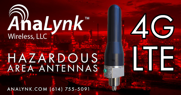
The Analynk CTX/CTM 4G LTE antennas are designed for use in “Hazardous-Classified” and Industrial-Hardened applications. The antennas are omnidirectional, with an average gain of 1.27dBi with a peak gain of 2.46 dBi. Two antenna versions are available, the CTX series has a 3/4” NPT mount, and the CTM series has an M20 mount. The antennas can be mounted on an Explosion Proof enclosure or conduit. The mounting base is made of heavy nickel-plated brass with an integrated TNC-F connector for ease of installation. The radome is optimized for rugged industrial applications while maintaining maximum radio frequency transmission and reception efficiency. The antennas have a built in Explosion Proof seal and may be mounted up to 18” away from the enclosure without an additional seal.

Get more information and download a specification sheet here.

Analynk Wireless
(614) 755-5091

Coming This June: Analynk's Hazardous Area 4G LTE Antenna

Hazardous Area 4G LTE Antenna

Analynk Wireless, an innovative manufacturer of hazardous area antennas and access point enclosures and wireless instrumentation for the process control industry, announced a 4G LTE antenna rated for Class I, Division 1 Groups C & D, ATEX, and IECEx Zone 1 areas.

4G, which stands for "Fourth Generation," is a standard developed by the International Telecommunications Union (ITU) in 2008, established explicitly by the ITU-R. (which deals with radio communications). Today, 4G is better known for its broadband capabilities and dramatically higher speed than 3G, which pioneered data access in the cellular space. 

The ITU standard mandated a minimum download speed of 100 Mbps, which was highly hypothetical at the time. In reality, several years later, carrier networks are only now realizing these goals. A wireless network must be capable of downloading at a rate of at least 100 Mbps to qualify as true 4G.

Analynk will introduce the new product this June 2021.

For more information, contact Analynk Wireless, LLC, 790 Cross Pointe Road, Columbus, OH 43230

Call them at 614-755-5091 or visit https://analynk.com.

Antennas Designed for Hazardous-Classified, Industrial Hardened Applications

Antennas Designed for Hazardous Areas

Wireless communication has seen increasing prevalence in the industrial process measurement and control field for several years.  It has provided years of reliable communications for monitoring and controlling processes, where using cables is either too costly or impractical. The absence of wires saves space, reduces the potential for damage, and simplifies modifications to the equipment layout. Implementing wireless communications in hazardous areas, whether through WiFi or other radio frequency channels, presents a particular set of challenges to successful implementation. Points of network access and further transmission and receiving equipment can require a level of isolation and hardening appropriate for the hazardous environment. In response to customers' desire to incorporate the technology across an ever-widening array of application scenarios, vendors continue developing and releasing new products and technologies that expand the potential for industrial wireless communication.

Many industrial process control operations can benefit from wireless connections between measurement and control devices. Analynk Wireless provides patented hazardous area explosion-proof antennas for industrial installations. Analynk antennas are operable across an extensive temperature range and provide substantial impact resistance, signal output, and third-party ratings for hazardous environments. These rugged antennas are for global application in the industrial process control field. Analynk hazardous area antennas are very robust and intended for industrial applications. All hazardous area antennas have UL listed Class I, Groups C and D, ATEX/IECEx Certification, and range of frequencies available- from 900MHz, 2.4GHz, and Cellular GPS, 4G, Iridium, and dual bands.

For more information, contact Analynk Wireless.
(614) 755-5091

Methods of Isolating Electrical Equipment in Hazardous Areas

Background

Combustion or fire is a chemical reaction in which a combustible material combines with an oxidant to release energy. Part of the energy release is used to sustain the explosion, by utilizing existing heat or creating a vacuum to consume more oxygen.  Within a hazardous environment there are three elements necessary for a fire or explosion:
  • A combustible material also known as a fuel 
  • Ignition source - electrical arcing or general heat
  • An oxidizer also known as oxygen
When a fuel, oxidizer and ignition source are present at the necessary levels, burning or explosion will occur. To reduce the possibility of fire or explosion, one of the key elements needs to be reduced or removed.

Another key factor in a fire or explosion are the explosive limits. These are the maximum and minimum concentration needed of a given combustible material to support a fire or explosion. To form an explosive mixture, the hazardous gas must have sufficient concentration levels. The minimum concentration of oxygen to combustible material is known as the lower explosive limit or LEL. If the concentration is below the LEL, it will not be flammable or have enough flammable material present. The same condition would apply if gas concentration is too rich, meaning it will not ignite because it will not have sufficient oxygen to sustain the fire or explosion. This is known as the upper explosive limit, or UEL. It should be noted that different gases will have different threshold limits.

In addition to the explosive limits, each hazardous material will have an autoignition temperature and a flashpoint. The flashpoint is the temperature at which the material will generate sufficient quantity of vapor to form an ignitable mixture. As the liquid is heated and reaches the flashpoint, autoignition could occur. An autoignition is the lowest temperature at which a combustible material will spontaneously ignite in a normal atmosphere. For example, if we have the heating of a combustible liquid, explosive vapors are created. As the material reaches the explosive limits creating the flashpoint. If the general atmosphere is increased, the autoignition temperature, fire, or explosion will occur.

To simplify, the specification of electrical devices into hazardous environments, IEC classification methods utilize autoignition, flashpoint, and explosive limits to place hazardous materials within groups.

The two predominant methods used for classification of hazardous environments are the NEC and IEC standards. IEC and NEC standards both classify the level of risk into three main categories:
  • Continuous
  • Occasional
  • Not normally present
All three categories provide the likelihood of an explosive atmospheric condition within the general environments. Within the IEC standard, the general risk categories are then classified as Zones. This reflects the physical material that could provide a potential fire or explosion. From liquids and gases, the area classifications are Zone 0, Zone 1, and Zone 2. By altering the physical material to dust or fibers, the area classification numerical value changes to Zone 20, Zone 21, and Zone 22.

Referring back to the necessary requirements for an explosive triangle, we know we need ignition source, oxygen, gas and or dust combustible material in the correct mixture within the atmosphere. In order to specify electrical devices and hazardous locations, we need to identify the general Zones within each area. When working with liquids or gas, we locate the most hazardous or flammable location directly above the material. Due to the possibility of the valve leaking, at the top of the containment structure we must classify the area as Zone 1. As we move further away from the possible explosive atmospheric condition the Zone classification would be reduced to Zone 2. By altering the combustible material properties to a solid form, the area classification above the material would be Zone 20. If the dust escapes the same failed valve, the external area around the same containment unit would be classified as Zone 21. As we continue to move away from the containment unit and with reduction of Category risk, the new classification for the general area would be Zone 22.

Now that we know combustible materials whether liquid, gas and or dust will have different upper and lower explosive limits, and we understand the general heat could be the ignition source, within the IEC standards the T rating specifies the maximum surface temperature an electrical device will create. As the temperature increases, the associate rating will decrease, meaningless heat will have a higher T rating, while an increase in surface temperature will reduce the T number.

As a recap the IEC standards classify hazardous areas as environments that could contain explosive vapors, gases, and/or dust within the atmosphere. The primary categories provide the risk levels as constant, occasional, and not likely. Since elements have a variety of flammability and the physical properties could be different, IEC standards segment the types of combustible materials into Zone classifications. The most hazardous is Zone 0 or Zone 20. By reducing the risk level to have occasional explosive atmospheres the Zone classification is Zone 1 or Zone 21 and further reduction of Category risks would change the hazards classification to Zone 2 or Zone 22
Flameproof enclosure
Flameproof enclosure for
wireless access point (Analynk

Methods of Isolation/Protection

Let's take a look at each method of protection and the general application. To ensure safety in a given situation, equipment is placed in protective level categories. As mentioned before Category 1 is the highest safety level, making Category 3 the lowest risk and safety level. The general 8 protective methods are:
  1. Flameproof enclosures
  2. Sand encapsulation
  3. Pressurization 
  4. Oil encapsulation 
  5. General encapsulation
  6. Increased safety
  7. Intrinsic safety
  8. Non-sparking
A flameproof enclosure method is a type of protection where devices that are capable of igniting an explosive atmosphere are built inside an enclosure. This protective method prevents the transmission of the explosion to the external atmosphere surrounding the enclosure. This method of protection would be suitable for applications on:
  • Power operated equipment
  • Switchgear
  • Motors
  • Any equipment that produces ignition source during normal operation.
Sand encapsulation is a type of protection in which the enclosure of the electrical apparatus is filled with a finely granulated material. This ensures electrical arcs occurring within the electrical apparatus will not ignite the surrounding atmosphere.

Pressurization is a method of protection by which the entry of a surrounding combustible material is prevented by maintaining a protective gas within the enclosure. This is generally accomplished by creating a higher pressure within the enclosure than the surrounding atmosphere. This protective method would be used for any power operated equipment.

Oil encapsulation is a type of protection in which the electrical apparatus or part of the electrical apparatus are immersed within an oil-based fluid. The general application for this type of protection would be used for:
  • Switchgear units
  • Circuit breakers
  • Transformers
Encapsulation is a type of protection in which the device that could ignite anexplosive atmosphere are enclosed within a resin. The material used would be resistant to environmental influences, heat and/or sparking from electrical components. The general application for this protective method would be used for:
  • Electrical circuit boards
  • Miniature motors
  • Valves
Increased safety is a type of protection where measures are taken to prevent the possibility of high temperatures and the occurrence of ignition. This method includes the interior and external portions of the electrical apparatus. The general application for this protective method would include:

Connection and distribution boxes
Luminaires
Measuring instruments and devices that do not normally produce ignition within operation

Intrinsic safety is a protective method to ensure that the available electrical and thermal energy in the system is always low enough that the ignition of the hazardous atmosphere cannot occur. This is achieved by ensuring that only low voltages and currents enter the hazardous area as well as all electrical supply and signal wires are protected by safety barriers. The general application for intrinsic safety would be used for:
  • Measuring and control engineering 
  • Data engineering
  • Low electrical valves
Non-sparking equipment and wiring process is a protective method where apparatuses are designed with low power levels and low stored energy. This ensures that arc produced during normal functionality of the equipment,  or as the result of equipment failure,  has insufficient energy to ignite the hazardous atmosphere. The general application for non-sparking protective methods would be used for:
  • Motors
  • Lighting
  • Junction boxes
  • Electrical equipment
All equipment certified for use in hazardous areas must be labeled to show the type and level of protection applied.

In summary hazardous locations could exist in multiple industries. The geographical location will dictate the general method used for classification. The European Standard or IEC provides guidance of risk into three main categories. These risk levels are then divided into Zones and have numerical values that relate to the possibility of explosive gases or dusts present within the atmosphere. Because combustible material could have a variety of explosive limits, the method of protection will be important. Nevertheless all electrical devices placed within hazardous environments will follow the device markings to ensure fire or explosion does not occur.

Hazardous Area Antennas

Gathering information in hazardous areas is critically important for plants to access. Wireless communications is vital for improved efficiencies, real-time monitoring of machinery and equipment, and the safety and well-being of personnel.

Hazardous area antennas from Analynk Wireless are designed and constructed for very rugged industrial applications. Furthermore, all Analynk hazardous area antennas  are UL  listed for Class 1, Groups C & D and have ATEX/IECEx Certification. Finally, a range of frequencies are available from 900MHz, 2.4GHz, Cellular, GPS, Iridium and dual bands.