Showing posts with label Analynk. Show all posts

Hazardous Area Wireless Equipment Enclosures Ease the Path to Implementation

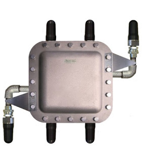
hazardous area wireless equipment enclosure with explosion proof antenna
Analynk hazardous area wireless equipment enclosures
are preconfigured for antenna connection.
Extending or establishing wireless connections in hazardous industrial environments presents a unique set of challenges. The equipment must be housed in an enclosure appropriately rated for the environment. Additionally, the antenna must extend outside the hazardous area rated equipment enclosure in order to properly function. The antenna must also carry a suitable rating for the hazardous area and provide an approved mating to the enclosure to preserve the safety integrity of the installation.

Analynk Wireless, innovators in the industrial wireless arena, provide a series of enclosures suitable for Class 1 Division 1 Groups C&D locations, as well as Class 1 Zone 1 applications. The enclosures are preconfigured to accommodate Analynk's hazardous area antenna, which provides access to a range of frequencies that include radio, cellular, and satellite communications.

The company also provides hazardous area rated enclosures for many popular industrial WiFi access points, preconfigured with antennas, equipment mounting bracket, and connection cables.

Share your industrial wireless communications challenges with the experts at Analynk Wireless. Combining your process expertise with their knowledge of wireless communications will produce the best solution.


Understanding Telecommunications Terminology

satellite orbiting earth for industrial process control wireless communications
Industrial wireless communications can include satellites
If you are delving into wireless communications for process control operations and expect to go beyond the use of industrial Wi-Fi, you are likely to encounter some concepts and lexicon that may be unfamiliar. A source of recognized standard definitions for industry specific terms will serve as a useful tool for understanding the specifics of radio communications.

Federal Standard 1037C, entitled Telecommunications: Glossary of Telecommunication Terms was issued by the General Services Administration late in the last century. It was superseded in 2001 by American National Standard T1.523-2001, Telecom Glossary 2000, published by Alliance for Telecommunications Industry Solutions commonly known as ATIS). The current version of the ATIS Telecom Glossary is available for use by the public. Find the glossary website, with its search engine, and either type a term to search for in the box or browse the extensive listings in alphabetical order. It's easy to use and can help you sort out the meanings of some industry specific terms.

Analynk Wireless is a wireless communications equipment provider to the industrial process control sector. Contact the application specialists at Analynk and share your wireless communication challenges.

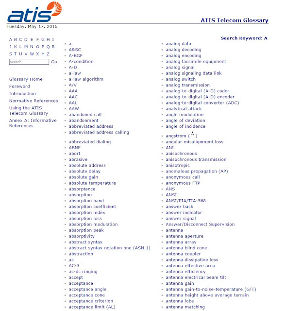
glossary of telecommunications terms
Screen shot of the glossary, showing search box in upper left area


Understand Fresnel Zones and Their Potential Impact On Your Process Signal Radio Transmission

wire frame rendition of ellipsoid representing Fresnel zone in radio transmission
Rendition of an ellipsoid, the representative shape
of a Fresnel zone
Most of us have been touched by wireless communications in the industrial process control setting. The majority of the installations are likely to be networks that operate similarly to the wireless network you may have in your home. Multiple points communicate through a network controller of some sort. The facility is flooded with signal coverage through multiple access points, so there may not be much need to consider signal propagation. Of course, this is an oversimplification. The point to be made is that, as an operator or implementer, making the actual signal connection is probably not going to be an issue in most cases.
How would you approach an application with a one mile transmission distance?
antennas and associated Fresnel zones and obstruction avoidance
Antennas with three Fresnel zones depicted and
obstruction that is outside the primary Fresnel zone
Courtesy Wikipedia
An extended transmission distance across an outdoor area requires more understanding of signal propagation and the factors that can impede the successful delivery of your
process data from transmitter to receiver. One concept that may come into play is the Fresnel zone.

I shall avoid any deep or technical approach to Fresnel zones, as my purpose is to provide the designer, technician, or implementer, who may have limited radio expertise, familiarity with the subject at a level empowering visualization of the concept to recognize the potential for its impact upon achieving a successful project. That said, a Fresnel zone, of which there an infinite theoretical number, is an ellipsoid shaped area extending between transmission and receiving antennas.  While we often consider the transmission path between two points as the popular "line of sight", an unobstructed straight line, radio frequency transmission is more accurately characterized by Fresnel zones. Being aware of the shape of the first, or primary, Fresnel zone for your application is an important element in identifying potential obstructions. A general practice is to keep the primary Fresnel zone at least 60% clear of signal obstructions, in order to maintain high wireless link performance.

There are numerous sources of Fresnel zone calculators online, but a strong recommendation to consult with your selected wireless equipment provider is in order here. Combine their expertise at applying their products with your application knowledge to reach the best outcome.

Practical Considerations for Wireless Transmission of Industrial Process Control Signals

Industrial process signal transmitter receiver or repeater Analynk
Industrial process signal transmitter
Rigging up the proper gear to establish wireless transmission of process measurement signals is generally a straight forward task. There are, however, a vastly different set of considerations than those for a wired transmission of the same signal. In order to select the right equipment for the job, some general comprehension of radio signals can be useful.

Radio wave frequencies are below the infrared range on the electromagnetic spectrum, thus their wavelengths are comparatively long. Three things can happen to electromagnetic radiation (radio waves) when encountering a barrier. 
  • Reflectance: The wave bounces off the barrier.
  • Transmittance: The wave passes through the barrier.
  • Absorbance: The wave is stopped.

Which of the three possibilities will occur depends upon a number of factors relating to the signal and the barrier, some of which include:
  • The wavelength of the radiation
  • The intensity of the radiation hitting the barrier
  • The chemical composition of the barrier
  • The physical microstructure of the barrier
  • The thickness of the barrier

Here is a conglomeration of knowledge items pulled together from a number of public sources that can be applied when considering a wireless installation.

Milliwatts (mW) are the common measurement unit of radio frequency (RF) power. A logarithmic scale of decibels, referencing 1 mW as the zero point, provides a useful way to express the comparative strength of RF signals. Using decibels, a signal strength of 1 mW is registered as 0 dBm. RF power attenuates according to a logarithmic function, so the dBm method of expressing RF power enjoys widespread use.

Industrial wireless communications applications in North America predominantly operate in either the 2.4 GHz or 900 MHz frequency range. Higher frequency will provide more bandwidth, but at the cost of reduced transmission distance and obstacle penetration. Lower frequency can require a larger antenna to attain the same signal gain.

Industrial wireless process signal antenna
Transmission power is not the only solution for delivering a signal. Low power signals can be successfully received by sensitive radio equipment. Reducing the data transmission rate can increase the functional sensitivity of the receiving equipment, too.

Be mindful of the existence or potential for RF background noise in your communications environment. A higher level of background noise can hamper the effectiveness of your equipment. The "noise floor" varies throughout the frequency spectrum and is generally below the sensitivity level of most equipment. Industrial environments can sometimes provide unusual conditions which may warrant a site survey to determine the actual noise floor throughout the communications area.

Lightning
Weather conditions can impact signal transmission
Radio transmission is susceptible to environmental elements on a variable basis. Since the environment can change without notice, it is useful to know the fade margin of a wireless installation. Fade margin expresses the difference between the current signal strength and the level at which the installation no longer provides adequate performance. One recommendation is to configure the installation to provide a minimum of 10dB of fade margin in good weather conditions. This level can provide sufficient excess signal strength to overcome the diminishing effects of most weather, solar, and interference conditions.


There are a number of simple methods to determine whether an installation has at least a 10 dB fade margin. Temporarily installing a 10dB attenuator on the system antenna, or installing a length of antenna cable that yields 10dB of attenuation will allow you to determine if the installation can accommodate 10dB of environmental impact on the signal. If the system operates suitably with the attenuation installed, you have at least that much fade margin.

RF signals attenuate with the square of the distance traveled, so if transmission distance is to be doubled, then the signal power must increase fourfold. 

True “line of sight” signal paths are found in a limited number of installations. The number, type, and location of obstacles in the signal path can have a significant impact on the signal and contribute to what is referred to as path loss. Probably the simplest way to reduce the impact of obstacles is to elevate the antennas above them.  Obstacles, in almost every case, are affixed to the earth, so their interference is reduced by elevating antennas to “see” over the obstacles.  

Forest
Wooded areas can be a significant barrier
When the signal path extends through an outdoor area, weather conditions have an impact on the path loss, with higher moisture levels increasing the loss. Large plants, most notably heavily wooded areas, can impose substantial reduction on RF signals and may require elevating antennas above the trees or using repeaters to route the signal around a forested area.

Industrial installations routinely present many reflective obstacles in the signal path. The transmitted signal may reflect off several obstacles and still reach the receiving antenna. The received signal strength will be the vector sum of all the paths reaching the antenna. The phase of each signal reaching the antenna can impact the total signal strength in a positive or negative way. Sometimes relocating the antenna by even a small amount can significantly change the strength of the received signal.

coiled antenna cable
Antenna cable 
Antenna cable contributes to signal attenuation. Use high quality cable of the shortest length possible to minimize the impact on performance.

Analynk Wireless has the equipment and expertise to help you deliver wireless process signals across the room, across the street, or across the globe.

Analynk Wireless and the Offshore Technology Conference 2016

Offshore oil and gas exploration and production rig or platform
Offshore Technology Conference 2016 brings together
participants in all sectors of the energy sector
Analynk Wireless will be exhibiting their full line of products May 2-5 2016 at the Offshore Technology Conference in Houston, Texas USA. OTC 2016 brings together professionals and vendors from all sectors of the energy industry, providing attendees access to leading-edge technical information, the industry’s largest equipment exhibition, and unrivaled opportunities for networking and the exchange of ideas and opinions. Analynk will be showcasing their wireless communication products that enable connections across the room or across the globe. Be sure and stop at their exhibit in booth 9056 and see how simply and effectively your wireless industrial process control and monitoring connections can be put into operation.
Learn more about the conference and register at the event website
Analynk Wireless is an innovative designer and supplier of wireless instrumentation for the process control industry, with products suitable for hazardous and non-hazardous locations. Transmitters, repeaters, receivers, and hazardous area antennas are available for 900 MHz, 2.4 GHz, cellular, GLONASS, GPS, and Iridium based communication of process signals.

Application Example - 900 MHz Wireless Delivery of Industrial Process Control Signal

We have a new video with an application example where wireless signal transmission provides a powerful solution. You can always get help with your applications by contacting us.

Process Control - Extending Wireless Process Signals

Diagram of wireless transmitter, repeater, and receiver for industrial process control
Analynk's wireless repeater extends your process signal
transmission distance or routes it around obstacles.
The simplicity of bringing a wireless connection to your process control application extends to overcoming one of the challenges that can arise due to extended distance or substantial obstacles between the transmitter and receiver. Analynk provides a repeater that can be strategically placed between transmitter and receiver to extend the overall transmission distance, or route the signal around obstacles that may otherwise degrade the transmission. The data sheet included below describes how easy it is to apply and provides all the technical details.

Contact Analynk with your process measurement and control wireless communication challenges and get get solid practical solutions.


Process Monitoring and Control - Where You Can Make Good Use of Wireless

Analynk empowers industrial process operators at any scale to bring the functional benefits of industrial wireless communication to their applications. The company provides easy to implement wireless hardware solutions that can be economically applied to even as single data point.

Talk a look at our short video for some application suggestions. Ramp up your ingenuity and develop ideas for your facility or operation. Contact the experts at Analynk for solutions. We enjoy hearing new and creative ideas for meeting process control challenges with wireless.


Installing Wireless Access Point in Hazardous Area

Industrial wireless network access point
Model AP320 Wireless Access Point
Courtesy Aruba Networks
In many technical endeavors, industrial process control being one, there are often collisions between what is necessary and what is desired. The incursion of wireless communications into the process measurement and control field has created such a collision between process engineers and IT managers. Granted, it's a cooperative and amicable collision, but a situation that can require the resolution of some incompatible interests.

For a number of reasons, it may be advantageous for the wireless network gear in the process section of a facility to conform to certain standards established for the larger scope of the organization. There can be real benefits to standardizing on particular brands or types of hardware. The tasks involved with back end management of network infrastructure are less complex when all the equipment is of the same vendor and product family. Provisioning, which includes initial setup, long term management, and unit loss management, is simplified when all the units are the same. Process engineers and operators pursue the same goal in standardizing on particular transmitters, valves, or other components that have multiple installations throughout a facility.
Industrial wireless access point explosion proof enclosure
Analynk Wireless Access Point Enclosure for
Hazardous Locations
The difficulty arises when the IT team's chosen wireless access point needs to be installed in an area classified as hazardous due to the potential for ignition of flammable or explosive gases and vapors. There is a solution, actually a fairly simple one.

Analynk manufactures enclosures for industrial wireless access points installed in hazardous locations. The current offering accommodates a range of units from Symbol, Cisco, Meru, Aruba, HP, and Motorola, with more models added regularly to accommodate additional wireless access points. Each access point enclosure is provided with UL listed explosion proof antennas, a mounting bracket designed for the target access point, and RF cables to make the antenna connections. Enclosures have penetrations specifically located to accommodate the target access point.
This arrangement allows for the deployment of the organization's preferred wireless access point in the hazardous process area.
Analynk Wireless specializes in industrial wireless communications. Your wireless communication challenges are welcome at Analynk, so make contact and share your application requirements. Combining your process expertise with Analynk's product specialization will produce a positive solution.

Analynk Expands Offering of Wireless Access Point Enclosures For Hazardous Areas

industrial wireless access point enclosure
Industrial Wireless Access Point Enclosure For
Hazardous Area
Analynk Wireless has developed a range of industrial wireless communications products suitable for use in hazardous areas. One product line, Hazalynk, includes enclosures for wireless access points that can be installed in hazardous areas. The company has recognized the special adaptations needed for installing wireless access points within hazardous areas in industrial process settings, and tailored the products to show their recognition of the needs of those responsible for providing industrial wireless communications in these specialized zones.

The Hazardous Area Access Point Enclosures are designed to accommodate the customer's selected access point device. Preconfigured models accommodate units from Cisco, Symbol, Meru, Aruba, Hewlett Packard, Motorola, and other brands. Custom arrangements are possible to accommodate most brands and models.

The matching enclosure for an access point will have:
  • Custom mounting bracket mating to the customer's access point.
  • UL listed enclosure for subject hazardous area, including antenna locations coordinated with access point device arrangement.
  • UL listed explosion proof antenna, one or more as need for the subject access point.
  • All hardware, mounting plate, and RF cables to simplify installation and startup
A product specialist can help you with the latest available information. Contact them to discuss your application and how to best fulfill your hazardous area wireless communication requirement. Watch the short video.


Out of the Box Thinking Delivers Benefits with Industrial Wireless Test Station

Industrial Tire
Tire manufacturer used wireless technology
to improve output
Wireless network communication has enjoyed continuously increasing rates of adoption in the industrial process control field for a number of years. Protocols and methodologies are generally well established and a wide range of products are available, making it less challenging to configure an application solution. As the manufacturers of industrial wireless devices have gained production efficiency and responded to an increasingly competitive market, the cost of implementing a wireless solution has become less of a barrier. Truly, industry is now in a phase where creativity and ingenuity will bring changes to traditional process and production operations to take full advantage of the untethering of many common measurement and control devices.

Traditionally, most measurement and control instrumentation was fixed in place by piping or cabling. While that is still the case throughout much of the industrial sector, opportunities are continuously emerging for wireless technology to provide improvement in performance and efficiency. I came across an example of how one manufacturer of tubeless tires devised a wireless test station to replace their existing wired version to:

  • Reduce maintenance by eliminating signal cables and power cables. No more cable damage from moving wired transmitters around the tire test area. 
  • Replace manual data logging with remote automatic data logging. 
  • Maintain or increase the accuracy of each measurement point. 
  • Allow a single test station to be employed easily at multiple locations throughout the factory. 

This was accomplished using readily available pressure transmitters, wireless transmitters, access points, receivers, and related hardware to provide a complete measurement system delivering test and measurement data to a remotely located data logger.

Use your creativity, your ingenuity. Get outside the box and examine your industrial process or production operation. Look for opportunities to sharpen your efficiency and improve outcomes. The prospects are good that there may be more gained from a wireless installation than the mere absence of cabling. Discuss your ideas with a wireless product manufacturer, solicit their recommendations, and evaluate the potential benefits to your operation.