Not Your Regular Lightning Protection Scheme

Lightining Strike
Predictive protection for sensitive electrical equipment
from lightning strikes
Lightning strikes constitute extreme releases of energy. A direct hit to your equipment has a high probability of rendering it unusable. The pathways of this destructive energy can be diffuse and unpredictable, leaving the best protection effort as disconnection of electrical equipment from wiring infrastructure and breaking the conductive path into the equipment.

Alokin Industries, manufacturer of Lightning Shield™ protection systems, identifies four threats to electrical equipment that originate from lightning activity.


  • Direct Lightning Strike: Direct lightning strikes to equipment result in high voltages flowing through the equipment grounding path or the circuit serving the equipment.
  • Nearby Lightning Strike: These strikes can induce voltage or current on building infrastructure conductors.
  • Lightning Ground Potential Rise ( L-GPR): This is the electrical energy flowing out from a strike that can saturate a building's grounding system.
  • Off-Voltage Events: Sags and spikes in service line voltage that can damage electrical equipment.
The Lightning Shield™ provides protection by disconnecting electrical equipment when a field energy increase is detected preceding a cloud to ground lightning strike. Isolating equipment from the AC power grid through a positive disconnecting means provides a high level of protection from cloud to ground lightning strikes and their residual impact. The controller will maintain isolated operation for a predetermined amount of time, then switch back to normal AC power. Equipment can be operated from battery or generator sourced power during the isolation period, if needed.

Lightning Shield™ provides predictive protection of electrical equipment by isolating equipment before the occurrence of a cloud to ground lightning strike. The system basically consists of a controller, detector, and whatever disconnecting means (contactor) are needed to accommodate the user's equipment.

Find out more about the Alokin Lightning Shield™, and share your equipment protection challenges with a product application specialist

New Hazardous Area Wireless Access Point Enclosures

Wireless Access point enclosure for hazardous area
Model AP 412 Hazardous Area Access Point Enclosure
Analynk Wireless has added two new entries to their line of wireless access point enclosures for use in hazardous areas. Each access point enclosure is shipped ready for installation of your access point device, with hazardous area antennas, cables, mounting bracket, and antenna cables included.

Analynk access point enclosures are preconfigured to house a specific manufacturer and model number access point. Review the product offering and see the long list of accommodated access points. If you want to use an access point not shown on the list, contact Analynk for a solution.

The new models are designed to house the Cisco 2802E and 3802E Dual Band Access Points. Data sheets for both are included below.

Analynk manufactures a diverse array of equipment utilized in establishing wireless connections between industrial process control devices. Share your wireless connectivity challenges with the experts at Analynk and get effective solutions.


Magnetic Level Indicators For Tank Level Measurement

magnetic level indicator for tank level measurement indication
Magnetic Level Indicator
Courtesy Orion
The magnetic level indicator (MLI), also called a magnetically coupled liquid level indicator or a magnetic level gauge, is in wide-spread use throughout process industries around the world. Originally designed as an alternative to sight glass gauges, MLIs are now commonly specified in new construction and plant expansions.

Principle of Operation

Magnetic level indicators use magnetic force couple the position of a float to a scale that indicates actual liquid level in a tank. The float movement and scale can be used to activate a switch or provide continuous level data via a transmitter. Unlike a sight glass, magnetic coupling allows the MLI to indicate liquid levels without direct contact between the externally-mounted visual indicator and the fluid in the vessel.

A magnetic field consists of imaginary lines of flux originating from the north and south poles and completely surround the magnet. This field acts on other objects (magnets or ferromagnetic materials) through these forces. When a magnetic field acts upon another body with sufficient force to influence it, the pair are said to be magnetically coupled to each other. In the case of a magnetic level indicator, the float is magnetically coupled to the indicator scale.

The MLI float, located inside the chamber and specifically engineered to provide proper buoyancy in the targeted fluid, dynamically tracks the surface of the liquid as it rises and falls. The magnet assembly inside the float generates a magnetic field that penetrates through the chamber wall to couple with the visual indicator.

Typical applications include:
  • Alkylation units 
  • Boiler drums
  • Feedwater heaters
  • Industrial boilers
  • Oil / Water separators
  • Process vessels
  • Propane vessels
  • Storage tanks
  • Surge tanks
  • Wastewater tanks

Advantages of the MLI

A magnetic level indicator is often used in applications where a sight glass (or glass sight gauge) is unsafe, environmentally risky, or difficult to see.

Typical shortcomings of glass sight gauges include:

  • High pressures, extreme temperatures, deteriorating seals, and toxic or corrosive materials may cause a risk of fugitive emission of dangerous substances. 
  • Some chemical materials within a process vessel or storage tank can attack the glass, causing discoloration of the sight gauge, thus decreasing level visibility. 
  • Liquid/liquid interfaces can be very difficult to read in a sight glass particularly if the liquids are of similar color. Clear liquids can also be difficult to see in a sight glass. 
  • Liquids that tend to coat or build-up on surfaces can hinder visibility by forming an opaque film on the glass. 
  • To cover a large measuring span, sight glass assemblies typically must be staggered using multiple sections. 
Key reasons for selecting an MLI over a sight glass are:
  • Improved safety due to the absence of fragile glass and a substantially reduced number of potential leak points. 
  • Greatly increased visibility 
  • Reduced maintenance. 
  • Easier initial installation and addition of transmitters and switches without interrupting the process 
  • Lower long-term cost of ownership and legitimate return-on-investment benefits. 
  • Single chamber measurement over 20 ft. (6 m) without staggering chambers.
When using a transmitter in conjunction with a magnetic level indicator, consider using a wireless connection to deliver the process signal from the transmitter to the monitoring and control unit. Analynk has effective solutions that can be easily implemented. A video shows an application example.

How Far Is Too Far with Wireless Process Signals?

antenna used for industrial wireless communications
Wireless communication technology, adapted for industrial use, has brought a host of benefits to companies bold enough to include it in their process control infrastructure. The use of wireless communications to deliver operating data from sensor to control station is no longer avant garde. The innovators, those first to deploy new technology, have long ago pushed the industrial process control world sufficiently up the learning curve to a point where applying wireless is a fairly straight forward matter.
Are there limits, practical or theoretical, to the length of a wireless connection?
Consider the bandwidth options for wireless transmission of a process signal. The 2.4GHz and 900MHz frequency bands each have their advantages for shorter distances in the range of a few feet to several miles. The ability to connect over any distance is impacted by a number of factors, not the least of which are allowable transmission power level and obstacles to the clear line of sight. One way to extend the range of a device is to install a repeater at some point along the transmission path. Repeaters will receive a fading process signal and transmit the signal at the full available strength, increasing the distance over which the information can be transmitted. Repeaters can also be useful for bypassing obstacles in the transmission path.

What if connection is needed over a longer distance?

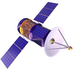
earth orbiting satellite used for process data communications
There are other options for bandwidth that can extend beyond a few miles. If service is available at transmission and receiving sites, cellular networks may be a workable option. Satellite data transmission is also a viable option that can provide global connectivity.

Distance is not really a great hurdle to overcome when it comes to establishing an industrial wireless connection. Share your industrial wireless challenges with application experts. Combining your process knowledge with their wireless expertise will produce effective solutions.

Piping & Instrumentation Diagrams in Process Control

electric power plant
All processes benefit from P&ID
P&ID's (Piping & Instrumentation Diagrams), or Process and Control Flow Diagrams, are schematic representations of a process control system, used to illustrate the piping system, process flow, installed equipment, instrumentation, and functional relationships among all the system components.

Intended to provide a comprehensive picture of all piping and associated hardware, including physical branches, valves, equipment, instrumentation and interlocks, the P&ID employs a set of standard symbols representing each component of the system such as instruments, piping, motors, pumps, etc. The use of standard symbols provides a universal depiction that can be read and understood by operators, technicians, outside contractors, and other similarly trained individuals.

P&ID’s can be very detailed and are generally the primary source from where instrument and equipment lists are generated, also being a very handy reference for maintenance and upgrades. P&ID’s also play an important early role in safety planning by enabling an understanding of the operating states and relationships of all components in the system.


Know Analynk Wireless - Introductory Video


Analynk Wireless is an innovative designer and supplier of wireless instrumentation for the process control industry. Instruments and equipment have been successfully implemented in numerous applications including temperature measurements, 4-20 mA bridges, discrete inputs/outputs, pulse inputs, lighting and pump controls. The company's products are used in both hazardous and non-hazardous locations. Analynk Wireless also manufactures a line of traditional wired process measurement and control instrumentation under the brand name Telmar Instruments.

Share your wireless connectivity challenges with the experts at Analynk. Combining your process knowledge with their expertise with produce effective solutions.