Analynk Custom Design Services

analynk wireless company logo
Analynk Wireless, in addition to their line of wireless communication products for process monitoring and control, offers custom design services for a broad range of applications in the industrial control arena.

The same engineering and design expertise that goes into every Analynk product can be channeled into specialty products or assemblies for your applications. Whether something as simple as a custom adapter board to facilitate connection between some dissimilar components or an embedded controller with a customized user interface, no application is without a solution.
  • Concept
  • Schematic design
  • PCB design
  • Firmware
  • Prototyping
  • Production
Share your ideas with the design team at Analynk. Combine your expertise with theirs to develop an effective solution.

Flow Control of Slurries and Liquids With Entrained and Suspended Solids

rubber lined pinch valve for industrial application
Cutaway view of  manually
operated pinch valve
Courtesy General Rubber
Industrial process control can involve the manufacture, storage, or transport of almost any imaginable fluid. Media can range from water to concrete, hydrogen gas to steam, and anything in between or outside of those boundaries. Valves are a favored control device for regulating fluid flow and they are available in uncountable varieties, each with particular aspects making them more or less suitable for a particular media or application.

Most industrial valves consist of a body, a stem, and some form of flow obstruction which is located within the media flow path. Operation of the stem repositions the obstruction to allow or block the flow. All of these valve types have a defined sealing surface where the obstruction contacts the body. They also have additional seals where the stem penetrates the body. These design features, while providing certain functions and application advantages, also add to the operational complexity and parts count for the valve.

There is a valve type with a simple operating principle that provides superior performance when the application involves certain media characteristics. It is called a pinch valve, and here is where it excels.
  • Resistance to abrasion and corrosion from slurries or fluids containing suspended solids and the ability to provide tight shutoff around particulates
  • Media and environmental temperature range -40 deg F to +300 deg F
  • Low to moderate operating pressure
  • Flow regulating capability and tight shutoff
  • Non clogging
  • Straight through full bore design with minimal flow resistance
  • Isolation of the valve body and workings from the media
  • Low parts count, low maintenance, easy repair/replacement
A pinch valve consists of a sleeve, through which fluid flows, and a means to compress or "pinch" the sleeve to reduce the open area inside the sleeve. The sleeves are most often fabricated from elastomers with various types of fiber reinforcement. Closure is commonly achieved through movement of one or two bars to squeeze the sleeve, providing throttling or positive closure. The flexibility of the sleeve material allows for tight shutoff, even with fluids containing suspended solids. The valves can be coupled with electric or pneumatic actuators and are available with industry standard connections. One valve variant has a body that can be pressurized to close the sleeve, without the need for a separate actuator. Pinch valves are available with and without an enclosing body.

You should be familiar with the capabilities and forms of this unique valve type. When confronted with certain application challenges, a pinch valve can be a superior solution.

Analynk is committed to excellence in process control, providing wireless communications for process signals, as well as explosion proof enclosures for wireless access points.

Signal Alarms for Process and Operations Monitoring

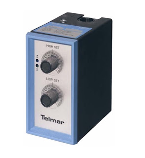
process control analog signal alarm Telmar Analynk
Telmar 500 Series Signal Alarm
Analynk
Signal alarms provide functionality related to a monitored process condition, which serves as the input to the device. High, low, or both high and low alarm points can be set on the device. When the process condition reaches one of the setpoints, a relay changes state. The relay, rated at 5.0 amperes at 120 VAC, can be used to annunciate the alarm occurrence or activate another device to take some other appropriate action. A number of input options are available that accommodate a broad range of process applications.

  • Thermocouple
  • Millivolt DC
  • RTD
  • AC or DC Current
  • Slide Wire
  • Strain Gauge
  • Tachometer
  • AC or DC Voltage
The standalone signal alarms can be incorporated into new control installations, or added to existing control systems to expand functionality. More information can be found in the data sheet included below, or reach out to Analynk and share your signal or process monitoring challenges and requirements.


Not Your Regular Lightning Protection Scheme

Lightining Strike
Predictive protection for sensitive electrical equipment
from lightning strikes
Lightning strikes constitute extreme releases of energy. A direct hit to your equipment has a high probability of rendering it unusable. The pathways of this destructive energy can be diffuse and unpredictable, leaving the best protection effort as disconnection of electrical equipment from wiring infrastructure and breaking the conductive path into the equipment.

Alokin Industries, manufacturer of Lightning Shield™ protection systems, identifies four threats to electrical equipment that originate from lightning activity.


  • Direct Lightning Strike: Direct lightning strikes to equipment result in high voltages flowing through the equipment grounding path or the circuit serving the equipment.
  • Nearby Lightning Strike: These strikes can induce voltage or current on building infrastructure conductors.
  • Lightning Ground Potential Rise ( L-GPR): This is the electrical energy flowing out from a strike that can saturate a building's grounding system.
  • Off-Voltage Events: Sags and spikes in service line voltage that can damage electrical equipment.
The Lightning Shield™ provides protection by disconnecting electrical equipment when a field energy increase is detected preceding a cloud to ground lightning strike. Isolating equipment from the AC power grid through a positive disconnecting means provides a high level of protection from cloud to ground lightning strikes and their residual impact. The controller will maintain isolated operation for a predetermined amount of time, then switch back to normal AC power. Equipment can be operated from battery or generator sourced power during the isolation period, if needed.

Lightning Shield™ provides predictive protection of electrical equipment by isolating equipment before the occurrence of a cloud to ground lightning strike. The system basically consists of a controller, detector, and whatever disconnecting means (contactor) are needed to accommodate the user's equipment.

Find out more about the Alokin Lightning Shield™, and share your equipment protection challenges with a product application specialist

New Hazardous Area Wireless Access Point Enclosures

Wireless Access point enclosure for hazardous area
Model AP 412 Hazardous Area Access Point Enclosure
Analynk Wireless has added two new entries to their line of wireless access point enclosures for use in hazardous areas. Each access point enclosure is shipped ready for installation of your access point device, with hazardous area antennas, cables, mounting bracket, and antenna cables included.

Analynk access point enclosures are preconfigured to house a specific manufacturer and model number access point. Review the product offering and see the long list of accommodated access points. If you want to use an access point not shown on the list, contact Analynk for a solution.

The new models are designed to house the Cisco 2802E and 3802E Dual Band Access Points. Data sheets for both are included below.

Analynk manufactures a diverse array of equipment utilized in establishing wireless connections between industrial process control devices. Share your wireless connectivity challenges with the experts at Analynk and get effective solutions.


Magnetic Level Indicators For Tank Level Measurement

magnetic level indicator for tank level measurement indication
Magnetic Level Indicator
Courtesy Orion
The magnetic level indicator (MLI), also called a magnetically coupled liquid level indicator or a magnetic level gauge, is in wide-spread use throughout process industries around the world. Originally designed as an alternative to sight glass gauges, MLIs are now commonly specified in new construction and plant expansions.

Principle of Operation

Magnetic level indicators use magnetic force couple the position of a float to a scale that indicates actual liquid level in a tank. The float movement and scale can be used to activate a switch or provide continuous level data via a transmitter. Unlike a sight glass, magnetic coupling allows the MLI to indicate liquid levels without direct contact between the externally-mounted visual indicator and the fluid in the vessel.

A magnetic field consists of imaginary lines of flux originating from the north and south poles and completely surround the magnet. This field acts on other objects (magnets or ferromagnetic materials) through these forces. When a magnetic field acts upon another body with sufficient force to influence it, the pair are said to be magnetically coupled to each other. In the case of a magnetic level indicator, the float is magnetically coupled to the indicator scale.

The MLI float, located inside the chamber and specifically engineered to provide proper buoyancy in the targeted fluid, dynamically tracks the surface of the liquid as it rises and falls. The magnet assembly inside the float generates a magnetic field that penetrates through the chamber wall to couple with the visual indicator.

Typical applications include:
  • Alkylation units 
  • Boiler drums
  • Feedwater heaters
  • Industrial boilers
  • Oil / Water separators
  • Process vessels
  • Propane vessels
  • Storage tanks
  • Surge tanks
  • Wastewater tanks

Advantages of the MLI

A magnetic level indicator is often used in applications where a sight glass (or glass sight gauge) is unsafe, environmentally risky, or difficult to see.

Typical shortcomings of glass sight gauges include:

  • High pressures, extreme temperatures, deteriorating seals, and toxic or corrosive materials may cause a risk of fugitive emission of dangerous substances. 
  • Some chemical materials within a process vessel or storage tank can attack the glass, causing discoloration of the sight gauge, thus decreasing level visibility. 
  • Liquid/liquid interfaces can be very difficult to read in a sight glass particularly if the liquids are of similar color. Clear liquids can also be difficult to see in a sight glass. 
  • Liquids that tend to coat or build-up on surfaces can hinder visibility by forming an opaque film on the glass. 
  • To cover a large measuring span, sight glass assemblies typically must be staggered using multiple sections. 
Key reasons for selecting an MLI over a sight glass are:
  • Improved safety due to the absence of fragile glass and a substantially reduced number of potential leak points. 
  • Greatly increased visibility 
  • Reduced maintenance. 
  • Easier initial installation and addition of transmitters and switches without interrupting the process 
  • Lower long-term cost of ownership and legitimate return-on-investment benefits. 
  • Single chamber measurement over 20 ft. (6 m) without staggering chambers.
When using a transmitter in conjunction with a magnetic level indicator, consider using a wireless connection to deliver the process signal from the transmitter to the monitoring and control unit. Analynk has effective solutions that can be easily implemented. A video shows an application example.