Showing posts with label industrial wireless. Show all posts

Analynk's Newest Wireless Access Point Enclosure for Hazardous Areas

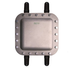
hazardous area wireless access point enclosure
New Model AP-621
Hazardous Area Wireless
Access Point Enclosure
Analynk Wireless has added again to its line of wireless access point enclosures for hazardous industrial locations. The access point enclosures are specifically targeted and designed to house specific wireless access points from a range of manufacturers, facilitating easy installation. Every model is provided with UL listed explosion proof antennas, a mounting bracket designed for the access point equipment, and RF cables to make the antenna connections. Enclosures have penetrations specifically located to accommodate the specified access point. Models are included to house a range of units from Symbol, Cisco, Meru, Aruba, HP, and Motorola, with more models added regularly to accommodate additional wireless access points.

The most recent addition is the model AP621 which accomodates  the Aruba AP-214 dual band access point. Analynk Wireless specializes in industrial wireless communications. Your wireless communication challenges are welcome at Analynk, so make contact and share your requirements. Combining your process expertise with Analynk's product specialization will produce an effective solution.

The datasheet for the new model is provided below. You can see all the models and their companion access points on the Analynk site.


Wireless Temperature Monitoring System Assures Safety in Firefighter Training Facility

firefighting training building burn building
Firefighters training at a burn building
Courtesy Fire Facilities
Fire Facilities designs and manufactures live firefighting training towers and buildings, referred to as burn buildings. Firefighters train in these structures honing their personal skills and developing team strategies for combating fires under live burn conditions. The training, because of the live fire in the structure, can be dangerous. Procedures and equipment are in place to minimize the risk posed to the training professionals.

Analynk Wireless designed and manufactures part of the safety and monitoring system for the Fire Facilities training structures. The system is suitable for worldwide use, as are the training structures. Sixteen temperature monitoring locations are established in the structure and monitored using the pyrometer developed by Analynk. The monitoring station provides alarm notification if the temperature in any of the monitored zones exceeds the level at which trainees can safely enter the area.
  • Monitor up to 16 channels of thermocouple input
  • Local temperature display on touchscreen HMI
  • Audible and flashing local alarm, plus relay contacts for connection of external devices
  • WiFi connection to smart phone or tablet for remote viewing of all operating information
  • Data logging of each channel to USB drive
  • Cloud connection for view access from anywhere with an internet connection
  • Email and text alerts
  • Monitoring station has NEMA 4 rating and is suitable for installation and operation in environments to -40 degrees
The Fire Facilities Pyrometer is another example of Analynk's capabilities in designing and building engineered products for specific applications. Share your process control product development challenges with the experienced professionals at Analynk, combining your concept with their design and engineering expertise to develop top flight product solutions.
pyrometer fire facilities

Industrial Wireless Communications Using a Single Transmitter and Multiple Receivers

water treatment plant
Water treatment plant
In planning a wireless installation for connecting process measurement instruments and equipment to monitoring and control stations, keep in mind that it is not necessary to maintain a one-to-one relationship among receivers and transmitters. A transmitter broadcasts the process signal on a designated channel. All the receiving devices set to that channel will receive the 256 bit encrypted signal. Each can decrypt the signal and convert the value to a common industrial analog signal for use as needed. The key takeaway is to recognize that once the process signal is transmitted, you have the ability to receive and use the signal anywhere within range of the transmitter. Effective range can extend from a few feet to several miles.

The beneficial applications for industrial wireless are limited only by your imagination and ingenuity. Share your ideas and challenges with the industrial wireless experts at Analynk, combining your own process knowledge with their application expertise to develop an effective solution.
wireless industrial communications with multiple receivers and one transmitter

Wireless Communications For Process Control

The incidence of wireless connections between process measurement devices and their monitoring and control stations has been expanding for years, with costs receding and performance increasing. Designers, engineers, and operators of industrial processes and facilities continue to find new applications and create continuous wireless connections to devices and equipment that were previously isolated by distance or other barriers. They are also saving cost, promoting flexibility, and reducing "clutter" in facilities by eliminating cables, conduits, and junction boxes previously used to transmit measurement signals between instruments and control or recording gear.

Analynk Wireless builds the wireless transmission and receiving equipment needed to establish connections among your process measurement and control equipment and instruments. Transmitters, receivers, and repeaters that are rugged and uncomplicated in their application. Share your wireless connectivity challenges with the experts at Analynk, combining your process knowledge with their technical expertise to develop an effective solution.


Preventing Cavitation in Process Control Valves

cutaway view industrial control valve special trim reduces cavitation
Special valve trim can help prevent
cavitation
Courtesy Flowserve - Kammer
Cavitation in process control valves results from a rapid drop in pressure as liquid passes through the valve. The condition results in the formation of vapor spaces or bubbles within the valve cavity. When the bubbles move downstream into a larger cross-sectional area, velocity decreases and liquid pressure increases. The higher pressure now surrounding the bubbles causes them to implode, producing shockwaves which propagate through the liquid. These shockwaves can cause metal fatigue and excessive wear on the internals of the valve. The collapsing bubbles also make a discernible sound with accompanying vibration. The cumulative effects of cavitation can cause rapid deterioration of valve internals, resulting in reduced control function, frequent need for service, or premature failure.

There are ways to mitigate cavitation. Some involve changes in the process, others, incorporating a properly designed and selected valve with trim that reduces or prevents the conditions that cause cavitation. The paper below is authored by Flowserve, a globally recognized manufacturer of process control valves under several brand names, and provides an in depth examination of the causes of cavitation, then continues with explanation of how their specialty valves are designed to overcome the conditions that promote it. At Analynk Wireless, we are not in the valve business, but recognize many of our customers operate fluid processes and would find the knowledge useful. There are detailed illustrations showing specific valve trim features that impede cavitation.

Analynk Wireless manufactures a comprehensive line of wireless receivers, transmitters, and accessories that enable process operators to establish signal connections across the room, across the plant, and across the globe.


Cooling Towers: Operating Principles and Systems

Industrial process cooling tower on building rooftop
Cooling towers are found in a wide range of sizes
and configurations
The huge, perfectly shaped cylindrical towers stand tall amidst a landscape, with vapor billowing from their spherical, open tops into the blue sky. Such an image usually provokes a thought related to nuclear power or a mysterious energy inaccessible to the millions of people who drive by power plants every day. In reality, cooling towers – the hyperboloid structures most often associated with the aforementioned nuclear power plants – are essential, process oriented tools that serve as the final step in removing heat from a process or facility. The cooling towers at power plants serve as both an adjuster of a control variable essential to the process and also as a fascinating component of the process behind power creation. The importance and applicability of cooling towers is extensive, making them fundamentally useful for industrial operations in power generation, oil refining, petrochemical plants, commercial/industrial HVAC, and process cooling.

In principle, a cooling tower involves the movement of water through a series of different parts or sections to eventually result in the reduction of its heat content and temperature. Water heated by the process operation is pumped through pipes to reach the tower, and then gets sprayed through nozzles or other distribution means onto the ‘fill’ of the tower, reducing the flow of water to appropriate levels; this maximizes the amount of surface area for contact between water and air. Electric motor driven fans pull air into the tower, and when the air meets the water, a percentage of the water evaporates, carrying heat from the water to the air and resulting in the water being cooled. The cooled water then gets transferred back to the process-related equipment, and absorbs heat again, allowing for the cycle to repeat. The process and associated dispersion of heat allows for the cooling tower to be classified as a heat rejection device, resulting in waste heat being rejected to the atmosphere. Towers depend on either evaporation to remove the process heat (open loop) or solely on air (closed loop), without evaporation, to reduce the water temperature.

Thanks to their range of applications, cooling towers vary in size from the monolithic structures utilized by power plants to small rooftop units. Removing the heat from the water used in cooling systems allows for the recycling of the heat transfer fluid back to the process or equipment that is generating heat. This cycle of heat transfer enables heat generating processes to remain stable and secure. The cooling provided by an evaporative tower allows for the amount of supply water to be vastly lower than the amount which would be otherwise needed. No matter whether the cooling tower is small or large, the components of the tower must function as an integrated system to ensure both excellent performance and longevity of use. Additionally, understanding elements which drive performance - variable flow capability, potential HVAC ‘free cooling’, the splash type fill versus film type fill, drift eliminators, nozzles, fans, and driveshaft characteristics - is essential to the success of the cooling tower and its use in both industrial and commercial settings.

So, the next time an imposing tower cracks the horizon underneath a pillar of drifting vapor, imagine all the components inside working together in a beautifully aligned system towards a common industrial goal. Such is the ingenuity of technology.

Analynk Wireless manufactures wireless communications equipment that can be used to establish radio connections between remote located cooling tower monitoring equipment and central control stations. Fan motor current, air or fluid flow and temperature characteristics, and outdoor air conditions are just some of the cooling tower performance parameters that can be monitored.

Attaining Close Temperature Control of Flowing Process Liquids

explosion proof temperature transmitter
Selection and placement of temperature sensors is a
critical element of achieving close temperature control.
Temperature control is a common operation in the industrial arena. Its application can range across solids, liquids, and gases. The dynamics of a particular operation will influence the selection of instruments and equipment to meet the project requirements. In addition to general performance requirements, safety should always be a consideration in the design of a temperature control system involving enough energy to damage the system or create a hazardous condition.

Let's narrow the application range to non-flammable flowing fluids that require elevated temperatures. In the interest of clarity, this illustration is presented without any complicating factors that may be encountered in actual practice. Much of what is presented here, however, will apply universally to other scenarios.
What are the considerations for specifying the right equipment?

KNOW YOUR FLOW


First and foremost, you must have complete understanding of certain characteristics of the fluid.
  • Specific Heat - The amount of heat input required to increase the temperature of a mass unit of the media by one degree.
  • Minimum Inlet Temperature - The lowest media temperature entering the process and requiring heating to a setpoint. Use the worst (coldest) case anticipated.
  • Mass Flow Rate - An element in the calculation for total heat requirement. If the flow rate will vary, use the maximum anticipated flow.Maximum Required Outlet Temperature - Used with minimum inlet temperature in the calculation of the maximum heat input required.


MATCH SYSTEM COMPONENT PERFORMANCE WITH APPLICATION


Heat Source - If temperature control with little deviation from a setpoint is your goal, electric heat will likely be your heating source of choice. It responds quickly to changes in a control signal and the output can be adjusted in very small increments to achieve a close balance between process heat requirement and actual heat input.

Sensor - Sensor selection is critical to attaining close temperature control. There are many factors to consider, well beyond the scope of this article, but the ability of the sensor to rapidly detect small changes in media temperature is a key element of a successful project. Attention should be given to the sensor containment, or sheath, the mass of the materials surrounding the sensor that are part of the assembly, along with the accuracy of the sensor.

Sensor Location - The location of the temperature sensor will be a key factor in control system performance. The sensing element should be placed where it will be exposed to the genuine process condition, avoiding effects of recently heated fluid that may have not completely mixed with the balance of the media. Locate too close to the heater and there may be anomalies caused by the heater. A sensor installed too distant from the heater may respond too slowly. Remember that the heating assembly, in whatever form it may take, is a source of disturbance to the process. It is important to detect the impact of the disturbance as early and accurately as possible.

Controller - The controller should provide an output that is compatible with the heater power controller and have the capability to provide a continuously varying signal or one that can be very rapidly cycled. There are many other features that can be incorporated into the controller for alarms, display, and other useful functions. These have little bearing on the actual control of the process, but can provide useful information to the operator.

Power Controller - A great advantage of electric heaters is their compatibility with very rapid cycling or other adjustments to their input power. A power controller that varies the total power to the heater in very small increments will allow for fine tuning the heat input to the process.

Performance Monitoring - Depending upon the critical nature of the heating activity to overall process performance, it may be useful to monitor not only the media temperature, but aspects of heater or controller performance that indicate the devices are working. Knowing something is not working sooner, rather than later, is generally beneficial. Controllers usually have some sort of sensor failure notification built in. Heater operation can be monitored my measurement of the circuit current.

SAFETY CONSIDERATIONS


Any industrial heater assembly is capable of producing surface temperatures hot enough to cause trouble. Monitoring process and heater performance and operation, providing backup safety controls, is necessary to reduce the probability of damage or catastrophe.

High Fluid Temperature - An independent sensor can monitor process fluid temperature, with instrumentation providing an alert and limit controllers taking action if unexpected limits are reached.

Heater Temperature - Monitoring the heater sheath temperature can provide warning of a number of failure conditions, such as low fluid flow, no fluid present, or power controller failure. A proper response activity should be automatically executed when unsafe or unanticipated conditions occur.

Media Present - There are a number of ways to directly or indirectly determine whether media is present. The media, whether gaseous or liquid, is necessary to maintain an operational connection between the heater assembly and the sensor.

Flow Present - Whether gaseous or liquid media, flow is necessary to keep most industrial heaters from burning out. Understand the limitations and operating requirements of the heating assembly employed and make sure those conditions are maintained.

Heater Immersion - Heaters intended for immersion in liquid may have watt density ratings that will produce excessive or damaging element temperatures if operated in air. Strategic location of a temperature sensor may be sufficient to detect whether a portion of the heater assembly is operating in air. An automatic protective response should be provided in the control scheme for this condition.

Each of the items mentioned above is due careful consideration for an industrial fluid heating application. Your particular process will present its own set of specific temperature sensing challenges with respect to performance and safety. Share your requirements with temperature measurement and control experts, combining your process knowledge with their expertise to develop safe and effective solutions.

Product Options Round Out Fulfillment of Application Requirements


Analynk Wireless, in addition to their standard products, can provide an extensive range of value added services to help customers quickly and effectively fulfill project requirements involving wireless communications and process control. Share your challenges with the wireless and process control experts at Analynk, combining your process knowledge with their wireless and control expertise to develop effective solutions.
Solar Powered Wireless Communications for Industrial Process Measurement and Control

solar energy power unit for industrial instruments measurement control
Analynk Model A650 Solar Power Supply
Wireless connections of process measurement and control equipment sometimes are accomplished in remote locations without readily available electric power. Analynk, as part of its full line of industrial wireless connectivity products, provides their model A650 Solar Power Supply for locations that require a small amount of DC power to operate instrumentation and an Analynk transmitter.

The power supply unit comes complete with solar panel, battery, charge controller, and NEMA 4 enclosure. Options are available to accommodate specific installation requirements. Custom units can be designed for larger power requirements and other special applications.

The data sheet below provides more detail. Share your wireless process measurement and control connectivity challenges with Analynk for effective solutions.


Process Connections - Wireless is Simple Solution to Many Challenges

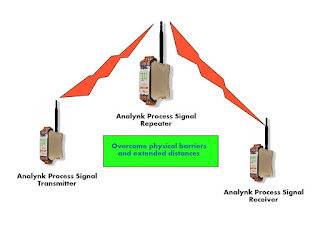
industrial wireless process control connection using transmitter, repeater, receiver
Wireless connections for industrial process signals
The operating personnel at almost every facility have something to which they would like to connect. Remotely located equipment, activities that require a human to be present to monitor operation, and other scenarios are all candidates for a wireless connection. Have you ever thought that it would be helpful to know more about the current status of a remotely located piece of gear, for example, the back-up generator located across the parking lot? Budgets, time constraints, cabling difficulties, and other factors seem to continually outweigh the benefits of making the connection and gathering the data. Those days are gone. In fact, they have been gone for some time.

Industrial wireless transmitters, receivers, and repeaters can be applied in place of wires, cables, conduit, trenches, overhead supports, and all the other hardware associated with a wired installation. Data is gathered using whatever process measurement hardware you prefer, just specify commonly used output signals like 4-20 mA, or a host of others. Connect the measuring device output to the transmitter input. Locate a receiver where you want the sensor information delivered. The transmitter converts the sensor analog signal to digital and the receiver converts back to analog. The connection can be accomplished in a very short amount of time without disturbance to the real estate between the two points.

How can I tell if the wireless connection can be accomplished without interference?
The transmission is accomplished in either the 900 MHz or 2.4 GHz band, delivering adequate range and power for most facility-wide applications. Obstructions can be overcome with the use of a strategically located repeater.
What about power needed to operate the sensors and wireless equipment?
Most process sensors have very small power requirements, as do the Analynk transmission units. Power, if line voltage is not available at the location, can be provided by batteries, or combination of battery and photovoltaic. Little power needs to be provided for operation.

There may be simple and effective wireless solutions to many of your remote monitoring challenges. Don't assume it is difficult, it is not. Don't assume it is expensive, it is not. Share your ideas and challenges with the experts at Analynk. Combining your facility and process knowledge with their technology and product expertise will lead to effective solutions.

Wireless Access Points Installed in Hazardous Locations


wireless access point enclosure for hazardous area Analynk
Hazardous area wireless access point enclosure
with explosion proof antennas.
Installing the IT department's chosen wireless access point in an area classified as hazardous due to the potential for ignition of flammable or explosive gases and vapors poses a challenge. While there can be real benefit to maintaining uniformity throughout the wireless network hardware, the gear installed in the office areas cannot be installed in a hazardous area without proper accommodation.

Analynk manufactures rated enclosures for industrial wireless access points, facilitating their installation in hazardous locations. Each access point enclosure is specifically targeted and designed to provide easy installation of specific wireless access points from a range of manufacturers. Every model is provided with UL listed explosion proof antennas, a mounting bracket designed for the target access point, and RF cables to make the antenna connections. Enclosures have penetrations specifically located to accommodate the target access point.The current offering accommodates a range of units from Symbol, Cisco, Meru, Aruba, HP, and Motorola, with more models added regularly to accommodate additional wireless access points.
The newly added AP620 is designed for the Motorola/Zebra AP-7532 Access Point
Analynk Wireless specializes in industrial wireless communications. Your wireless communication challenges are welcome at Analynk, so make contact and share your application requirements. Combining your process expertise with Analynk's product specialization will produce an effective solution.


Increasing Generator Set Starting Reliability

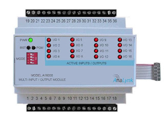
I/O expansion module for industrial wireless transmitter or receiver
Genset monitoring application is ideal for use
of the A16000 Expansion Module
Standby electric generators, often powered by gas or diesel fuel, are critical to maintaining operations in the face of electric power outages. Generator sets for industrial or commercial use are often provided with onboard controls to automatically start the unit, activate a transfer switch, and take the unit back off-line when grid power is restored.

A generator set is a risk mitigation asset, intended to prevent loss of operations when certain adverse conditions occur. Power failures are generally infrequent, so the equipment remains idle most of the time. Automatic controls can test run the unit periodically, but continuous monitoring of a few points on the equipment can provide information that increases the assurance that the unit will start when commanded. Delivering the data to an operations center for monitoring and storage for analysis provides a supervisor a snapshot of unit readiness in real time, anytime.

Some items to monitor that can increase your assessment of startup reliability:

  • Fuel Level - Clearly, knowing the current fuel level is useful. Being able to read the engine fuel level from your operations center saves technician time and provides a continuous means of estimating available generator runtime.
  • Engine Block Heater - Measure the current flowing to the engine block heater to make sure the heater is functioning properly. 
  • Battery - A voltage reading provides indication of battery health.
  • Ambient Temperature - While not essential, logging temperature along with the other items can provide some useful data that may reveal some correlations.
  • Generator Controller Fault Indicators - If the generator control system provides any outputs that will indicate detection of a fault, monitoring their status at the facilities office brings the data to where it can be acted upon immediately.
There may be other aspects of a generator set that can be monitored during standby to increase the assurance of a startup on command. A careful assessment of each system in place will reveal the possibilities.

Analynk manufactures all the transmitters and sensors necessary to deliver the data points needed. With many generators located remotely from the point where the data should be delivered, Analynk's wireless communications products can be employed to deliver all the data from the generator to the facilities or operations center without having to install any cabling between the locations.

Reach out to Analynk with your performance or process monitoring and data delivery challenges. Combing your process and facilities knowledge with their product application expertise will produce effective solutions. 

RTD or Thermocouple for Your Temperature Measurement Application?

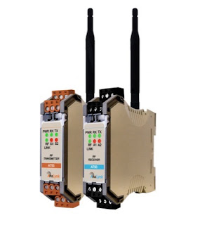
industrial process signal wireless transmitter and receiver
Wireless transmission of temperature signals can be
easily accomplished with Analynk transmitters and receivers
Proper temperature sensor selection is key to getting useful and accurate data for maintaining control of a process. There are two main types of temperature sensors employed for industrial applications, thermocouple and resistance temperature detector (RTD). Each has its own set of features that might make it an advantageous choice for a particular application.

Thermocouples consist of a junction formed with dissimilar conductors. The contact point of the conductors generates a small voltage that is related to the temperature of the junction. There are a number of metals used for the conductors, with different combinations used to produce an array of temperature ranges and accuracy. A defining characteristic of thermocouples is the need to use extension wire of the same type as the junction wires, in order to assure proper function and accuracy.

Here are some generalized thermocouple characteristics.

  • Various conductor combinations can provide a wide range of operable temperatures (-200°C to +2300°C).
  • Sensor accuracy can deteriorate over time.
  • Sensors are comparatively less expensive than RTD.
  • Stability of sensor output is not as good as RTD.
  • Sensor response is fast due to low mass.
  • Assemblies are generally rugged and not prone to damage from vibration and moderate mechanical shock.
  • Sensor tip is the measuring point.
  • Reference junction is required for correct measurement.
  • No external power is required.
  • Matching extension wire is needed.
  • Sensor design allows for small diameter assemblies.

RTD sensors are comprised of very fine wire from a range of specialty types, coiled within a protective probe. Temperature measurement is accomplished by measuring the resistance in the coil. The resistance will correspond to a known temperature. Some generalized RTD attributes:

  • Sensor provides good measurement accuracy, superior to thermocouple.
  • Operating temperature range (-200° to +850°C) is less than that of thermocouple.
  • Sensor exhibits long term stability.
  • Response to process change can be slow.
  • Excitation current source is required for operation.
  • Copper extension wire can be used to connect sensor to instruments.
  • Sensors can exhibit a degree of self-heating error.
  • Resistance coil makes assemblies less rugged than thermocouples.
  • Cost is comparatively higher

Sensors are often part of a transmitter assembly that provides an output signal suitable for connection to controllers or monitoring instrumentation. Challenges of distance can be easily overcome using Analynk's wireless process control connection products. Whether the distance is meters or miles, Analynk has a solution that is effective and simple to apply.

Each industrial process control application will present its own set of challenges regarding vibration, temperature range, required response time, accuracy, and more. Share your process temperature measurement requirements and challenges with a process control instrumentation specialist, combining your process knowledge with their product application expertise to develop the most effective solution.

Specialty Valve for Transmitter Isolation

specialty transmitter isolation valve
Transmitter Isolation Valve
Courtesy PBM Valve Solutions
Fluid process control applications frequently employ tanks and vessels as part of the processing chain or for storage and holding. Level transmitters can be installed on the tank to provide indication of liquid level. While there are numerous combinations of fittings and valves that could be used to mount and connect the transmitter to the tank, one manufacturer, PBM Valve Solutions, has designed a specialized valve intended to mate a transmitter to a tank fitting with great advantage.

The specialized transmitter isolation valve minimizes dead space to prevent media residue buildup. It can be configured to accommodate CIP and drainage without process interruption. Calibration ports and industry standard mountings allow for broad application throughout the fluid process control industries.

Establishing a connection between the transmitter and its associated monitoring or control equipment is a specialty of Analynk Wireless. Analynk provides end to end solutions for delivering transmitter signals using wireless communications that can span across the room or around the globe. Reach out to Analynk for effective and easy to implement wireless solutions.

Explosion Proof Antennas For Wireless Communications in Hazardous Industrial Settings

explosion proof antenna for industrial wifi wireless communications
CTX Series Explosion Proof Antenna
Analynk
Wireless connections between process measuring and control devices brings several benefits to an industrial operation. The signal cable free installation saves valuable time and space, reduces damage exposure, and simplifies process equipment layout modifications.

Implementing wireless communications in hazardous areas, whether through WiFi or other radio frequency channels, poses a unique set of challenges to successful implementation. Points of network access and other transmission and receiving equipment will require a level of isolation and hardening appropriate for the hazardous industrial environment. Specialized explosion proof enclosures can house the needed equipment, but antennas must extend outside these metal enclosures and into the hazardous environment in order to transmit and receive process signals. This imposes rigorous requirements on antenna design and construction.

Analynk Wireless manufactures patented UL listed hazardous area explosion proof antennas for industrial installations.  Their CTX and CTM series antennas carry an array of third party approvals and are suitable for use in a broad range of hazardous environments. Models can accommodate WiFi and other RF communications across frequency bands commonly utilized in industrial settings, as well as cellular and satellite communications.

Data sheets for the CTX and CTM Series antennas are included below for more detail. Share your wireless communication challenges and application questions with the experts at Analynk and work together to produce the best solutions.

Analynk Further Expands Line of Hazardous Area Wireless Access Point Enclosures

hazardous area wireless access point enclosure with antennas
New AP608 Explosion Proof Access Point Enclosure
For Meru AP-1020e
Analynk Wireless has added three new entries to their line of wireless access point enclosures for use in hazardous areas. Each enclosure is shipped ready for installation of your access point device, with hazardous area antennas, antenna cables, and custom access point mounting bracket included.

Analynk access point enclosures are preconfigured to house a specific manufacturer and model number access point. Review the entire product offering and see the long list of accommodated access points. If you want to use an access point not shown on the list, contact  Analynk for a solution.

The new models and their matching access point.
The hyperlinks above will open data sheets for the respective units.

Analynk manufactures a diverse array of equipment utilized in establishing wireless connections between industrial process control devices. Share your wireless connectivity challenges with the experts at Analynk and get effective solutions.

Flow Control of Slurries and Liquids With Entrained and Suspended Solids

rubber lined pinch valve for industrial application
Cutaway view of  manually
operated pinch valve
Courtesy General Rubber
Industrial process control can involve the manufacture, storage, or transport of almost any imaginable fluid. Media can range from water to concrete, hydrogen gas to steam, and anything in between or outside of those boundaries. Valves are a favored control device for regulating fluid flow and they are available in uncountable varieties, each with particular aspects making them more or less suitable for a particular media or application.

Most industrial valves consist of a body, a stem, and some form of flow obstruction which is located within the media flow path. Operation of the stem repositions the obstruction to allow or block the flow. All of these valve types have a defined sealing surface where the obstruction contacts the body. They also have additional seals where the stem penetrates the body. These design features, while providing certain functions and application advantages, also add to the operational complexity and parts count for the valve.

There is a valve type with a simple operating principle that provides superior performance when the application involves certain media characteristics. It is called a pinch valve, and here is where it excels.
  • Resistance to abrasion and corrosion from slurries or fluids containing suspended solids and the ability to provide tight shutoff around particulates
  • Media and environmental temperature range -40 deg F to +300 deg F
  • Low to moderate operating pressure
  • Flow regulating capability and tight shutoff
  • Non clogging
  • Straight through full bore design with minimal flow resistance
  • Isolation of the valve body and workings from the media
  • Low parts count, low maintenance, easy repair/replacement
A pinch valve consists of a sleeve, through which fluid flows, and a means to compress or "pinch" the sleeve to reduce the open area inside the sleeve. The sleeves are most often fabricated from elastomers with various types of fiber reinforcement. Closure is commonly achieved through movement of one or two bars to squeeze the sleeve, providing throttling or positive closure. The flexibility of the sleeve material allows for tight shutoff, even with fluids containing suspended solids. The valves can be coupled with electric or pneumatic actuators and are available with industry standard connections. One valve variant has a body that can be pressurized to close the sleeve, without the need for a separate actuator. Pinch valves are available with and without an enclosing body.

You should be familiar with the capabilities and forms of this unique valve type. When confronted with certain application challenges, a pinch valve can be a superior solution.

Analynk is committed to excellence in process control, providing wireless communications for process signals, as well as explosion proof enclosures for wireless access points.

How Far Is Too Far with Wireless Process Signals?

antenna used for industrial wireless communications
Wireless communication technology, adapted for industrial use, has brought a host of benefits to companies bold enough to include it in their process control infrastructure. The use of wireless communications to deliver operating data from sensor to control station is no longer avant garde. The innovators, those first to deploy new technology, have long ago pushed the industrial process control world sufficiently up the learning curve to a point where applying wireless is a fairly straight forward matter.
Are there limits, practical or theoretical, to the length of a wireless connection?
Consider the bandwidth options for wireless transmission of a process signal. The 2.4GHz and 900MHz frequency bands each have their advantages for shorter distances in the range of a few feet to several miles. The ability to connect over any distance is impacted by a number of factors, not the least of which are allowable transmission power level and obstacles to the clear line of sight. One way to extend the range of a device is to install a repeater at some point along the transmission path. Repeaters will receive a fading process signal and transmit the signal at the full available strength, increasing the distance over which the information can be transmitted. Repeaters can also be useful for bypassing obstacles in the transmission path.

What if connection is needed over a longer distance?

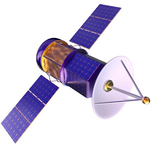
earth orbiting satellite used for process data communications
There are other options for bandwidth that can extend beyond a few miles. If service is available at transmission and receiving sites, cellular networks may be a workable option. Satellite data transmission is also a viable option that can provide global connectivity.

Distance is not really a great hurdle to overcome when it comes to establishing an industrial wireless connection. Share your industrial wireless challenges with application experts. Combining your process knowledge with their wireless expertise will produce effective solutions.

Piping & Instrumentation Diagrams in Process Control

electric power plant
All processes benefit from P&ID
P&ID's (Piping & Instrumentation Diagrams), or Process and Control Flow Diagrams, are schematic representations of a process control system, used to illustrate the piping system, process flow, installed equipment, instrumentation, and functional relationships among all the system components.

Intended to provide a comprehensive picture of all piping and associated hardware, including physical branches, valves, equipment, instrumentation and interlocks, the P&ID employs a set of standard symbols representing each component of the system such as instruments, piping, motors, pumps, etc. The use of standard symbols provides a universal depiction that can be read and understood by operators, technicians, outside contractors, and other similarly trained individuals.

P&ID’s can be very detailed and are generally the primary source from where instrument and equipment lists are generated, also being a very handy reference for maintenance and upgrades. P&ID’s also play an important early role in safety planning by enabling an understanding of the operating states and relationships of all components in the system.